FL7006/FL7030/FL7218/FL7040/FL7060Kit
Rev J 19
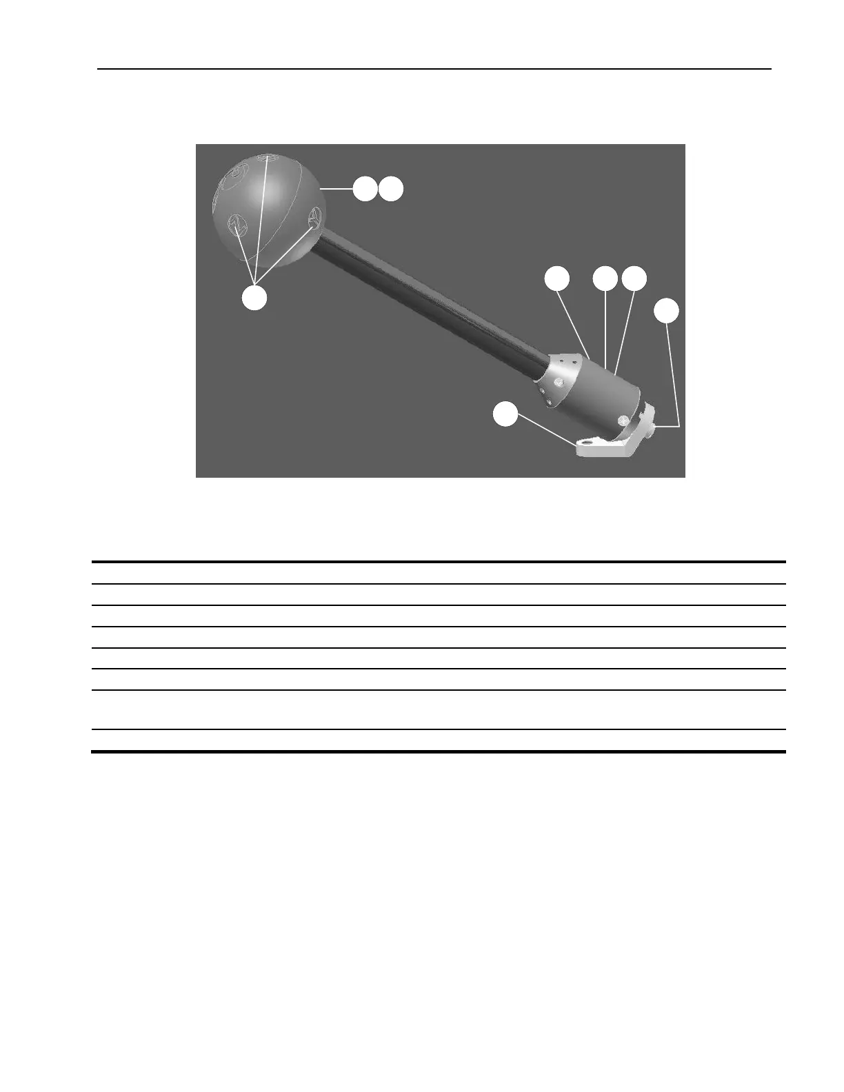
3.4.2 FL7218/FL7040/FL7060 Probe
Figure 3-2: FL7218/FL7040/FL7060 Probe Features
Table 3-2. FL7218/FL7040/FL7060 Probe Features
Three antennas sensor elements to sense electric field.
Protects and supports the sensors
Housing & Protective Cover
Protects and shields the probe electronic components
Routes laser (optical) power and commands to probe
Routes (optical) transmit data from probe
Provides mount via ¼ -20 screw.
For mounting probe with a selected sensor axis aligned to a mounting screw axis. This is the
normal mounting position when the probe is used to measure individual field axis (X, Y, Z)
X, Y, Z markings indicate the tips of each dipole antenna.