FL7006/FL7030/FL7218/FL7040/FL7060Kit
Rev J 17
source. Spatial variations occur in close proximity to a radiating antenna creating a test field or in a GTEM
with expanding dimensions, causing noticeable field changes with propagation distance. Caution should be
exercised in the use of the composite measurement of isotropic probes when there is significant spatial
variation in the field over the dimensions the probe. Repositioning the probe to adjust for the individual offset
of each axis may produce a more consistent result.
3.3.2.9 Alignment with E-Field
To improve measurement accuracy, it is recommended that one axis of the probe always maintain alignment
with the E-field being measured. This becomes more important the higher the E-field. See Appendix A for
guidance on orienting stalk type Field Probes.
3.3.2.10 Calibration Reports
Each Field Probe is supplied with an initial calibration report and data. Within this data is a set of Correction
Factors that should always be used when making field measurements. Correction Factors are typically
supplied as multipliers as well as a dB value.
It is the responsibility of the user to apply Correction Factors. This can be done manually or through the use
of a Field Monitor such as the Models FM7004A or VM7000 as well as with automated test software such as
emcware
®
.
Correction Factors are always supplied by frequency. It is up to the user to select the Correction Factor that
applies to the frequency of the E-field being measured. Quite often measurements are desired at frequencies
that are not included in the Correction Factor list. In these situations, it is recommended that linear
interpolation be used between adjacent frequencies.
Typically, Correction Factors are supplied at one amplitude with that amplitude being toward the lower end of
the specified operating range. These Correction Factors can be applied throughout the entire amplitude range
of the probe.
Additionally, linearity data is provided in the calibration report. This data is useful for understanding how
linear the probe is over a portion of its specified operating range. The provided linearity data can be used as
Correction Factors to correct measurement values over amplitude in addition to the Correction Factors
supplied over frequency.
Most calibration reports will also contain a set of isotropic deviation values which are useful in understanding
how much measured values can vary when alignment of one axis with the E-field is not maintained.
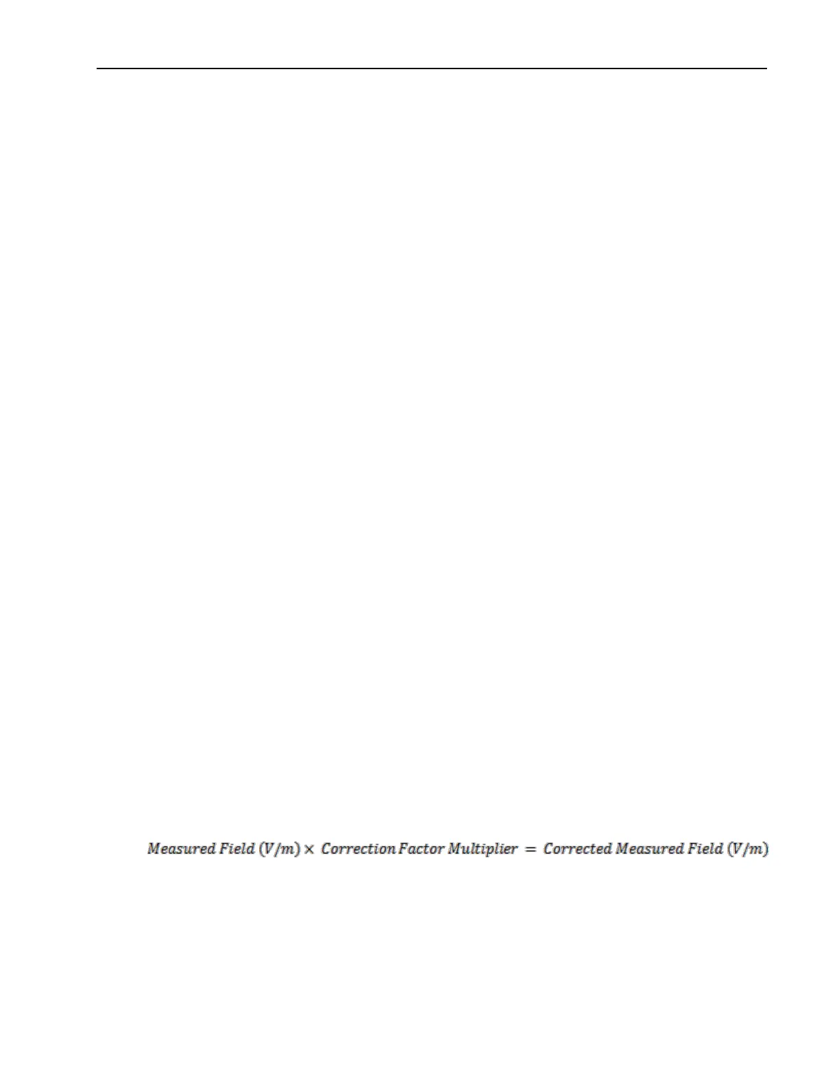
3.3.2.10.1 Applying Correction Factor Multipliers
To apply Correction Factor multipliers, simply multiply the measured field by the Correction Factor
multiplier. This will yield the corrected field measurement in V/m.
3.3.2.10.2 Applying dB Correction Factors
To apply a dB Correction Factor, the measured field provided by the probe must first be converted to a
logarithmic scale. Once the field is in a log scale, the dB Correction Factor can simply be added. A
conversion is then required to bring the corrected field value back to the original V/m units. The equations
below show each step in this correction process.