Laminated edge
must face down
Figure 3
H1
H1
H1
H1
E
Barrel Nuts
on inner side
B
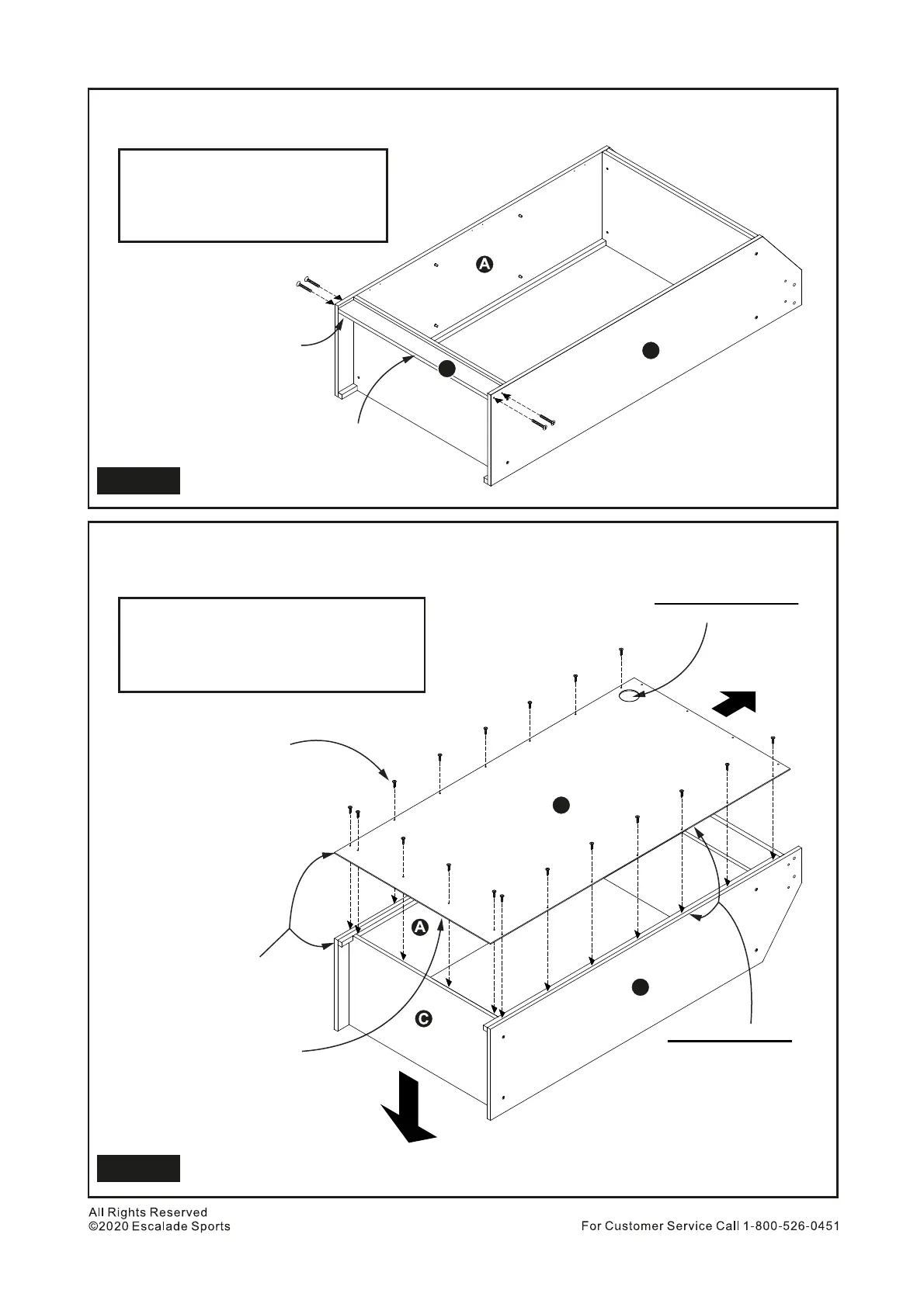
Install Part E between Parts A and B and attach it using 4 pcs H1 Phillips Flat Head Bolts.
See Figure 3. Tighten, but do Not over tighten or strip out H1 Bolts.
7.
H1
E
Phillips Screw Driver
Phillips Flat Head Bolt - 4 pcs
Base Cross Panel - 1 pc
PARTS REQUIRED
Carefully Flip the Lower Cabinet Assembly with front side face down onto the floor, then install Part F
to back of Lower Cabinet Assembly using 18 pcs H9 Phillips Round Head Screws (Screws installed to
edge side of Part A, B & C. See Figure 4.
8.
H9
F
Phillips Screw Driver
Phillips Round Head Screw - 18 pcs
Lower Back Panel - 1 pc
PARTS REQUIRED
Figure 4
Front
Top
Important Note:
Must be flush
Raw wood on
this back side
Laminate to inside
F
B
8
IMPORTANT NOTE:
LED unit battery box cable hole on this top side
Important NOTE:
Make sure edge of top,
left and right sides are flush
with lower cabinet edge.
All screws are H9