1 2 3 4 5 6 7 8
A
B
C
D
87654321
D
C
B
A
ISSUE
DRAWING NO.
23425
DRAWING TITLE
Drawn by:
DATE
Filename
ECO No. DESCRIPTION OF CHANGE
J:\Development Projects\P7 Amp\Transformer Design\L911TX 1.ddb - Documents\L911TX 1.sch
A & R Cambridge Ltd.
Pembroke Avenue
Denny Industrial Centre
Waterbeach
Cambridge CB5 9PB
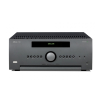
POWER TRANSFORMER FOR P7 115/230V
Circuit Diagram
L911TX
KAL
6-Mar-2002
INITIALS
Date Printed
1 1Sheet of
Notes
BROWN
WHITE
BLACK
BLUE
115V ac
115V ac
PRIMARY
SECONDARY
6 WAY CONN P N 3
6 WAY CONN P N 1
6 WAY CONN P N 6
6 WAY CONN P N 4
+
10000uF
TEST CIRCUIT (PER OUTPUT)
2A load
+VOUT
-VOUT
6 way MOLEX 39-01-2065
2 way MOLEX 39-01-3028
PRIMAR ES
SECONDARY 7
95max
POTTING COMPOUND
Rubber insulating pad
1
2
1
2
1
2
1
2
1
2
1
2
RED
OR
RED
OR
RED
OR
RED
OR
RED
OR
RED
OR
RED
OR
1
2
12
5 1
3
46 2
2 way6 way
Pin outs of Molex connectors
As viewed looking down at the end
the wires enter the connector
1
2
3
4
5
6
SCREEN WIRE GRN/YELL
145mm dia max
AC N
100C THERMAL TRIP
NORMALLY CLOSED
SCREEN W RE
M4 CRIMP EYELET
Transformer Specification For 115/230V P7 transformer
Arcam Part Number L911TX
Material Safety Specification
1. Winding Wire to be Grade 2 (130C rating) to BS 60317-4 1995
2. Mylar Polyester Insulator 130C Rated
3. Potting Compound PC3502 E135297(M)
Mechanical Specification
1. Middle of transformer to be potted (as shown).
2. Primary windings connect to 6 way MOLEX connector 39-01-2065.
Secondary
44476-3112.
MOLEX connectors have pin numbers indicated on them.
3. Primary wires are enclosed in a common sleeve. Each secondary
winding is individually sleeved.
Use PVC sleeving.
4. All wire lengths in mm. Lengths are +5.0, -0
5. Please adhere rubber insulating pad to bottom of transformer as shown.
Electrical Specification
1. Transformer to have dual 115V primaries to allow parallel operation for
115V input and series operation with 230V input.
2. Transformer input voltage range
115V -18% +14% (97.5V to 132 5V)
230V -18% +14% (195V to 265V)
3. Transformer to have 7 secondary windings as show in the adjacent
drawing.
4. Loaded DC voltages specified at 230V AC in (with transformer primaries
in series)
5. Each secondary winding to have a full wave (4diode) bridge to produce a
single DC rail.
(AS shown in diagram)
Output Capacitance to be 10000uF per rail.
VOUTmin = 52V dc @ Io = 2A (with 230V AC in) See dwg
This figure to be the minimum voltage on the reservoir capacitor as shown
in the diagram
RESETTABLE
1
2
2WAY 10-11-2023 molex
M4 CRIMP EYELET
LEADS EXIT FROM BOTTOM
2 way MOLEX 39-01-3028
SECONDARY 1
FOR LENGTH OF SECONDAR ES
SECONDARY LENGTH
1
2
3
4
5
6
7
520
560
550
570
570
610
650
Lead Out Changes
Voltage on Reservoir Capacitor
52V
10mS
THERMAL TRIP
2WAY 10-11-2023 molex
200mm
SEE TABLE BELOW
280mm
280mm
D4-12-2001KAL Mechanical Changes
Lead Out Changes to suit new wiring arrangement in amplifier
M12 Threaded Brass Insert
NSERT TO ALLOW 30mm DEPTH OF THREAD
SECONDARY WIRES
LEADS EXIT FROM BOTTOM
PRIMARY WIRES
UL94- V0
Connector Latch
VOUT min
105-03-2002KAL

 Loading...