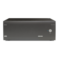
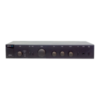
Fmj P1 Amplifier circuit description
by A.Moore
P
roduct description
The
P1 has been has been designed to
provide unsurpassed sound quality, the main
design features are as follows.
o
Gain switchable between Arcam gain
and THX gain (29dB closed loop) a 0dB
signal equates to 100 watts into 8
ohms.
o Input switchable between unbalance
phono and balance XLR.
o The amp is capable of producing >180
watts of sinusoidal output into an 8
ohm load and greater than 300 watts
into a 3.2 ohm load (subject to thermal
dissipation limits).
o Relay coupled for silent on/off
operation.
o Opto-isolated fault and control lines to
the control PCB.
o DC coupled signal path with
integrating servo to remove residual
DC errors.
o Instantaneous safe operating area
protection.
o Exceptionally low harmonic and
intermodulatiion distortion.
o Flat frequency response.
o Fast and asymmetric slew rate.
o
High damping factor
o Unconditionally stable into loads of
upto +/- 90-degree phase.
P
ower supply/Control description
The
mains input is applied via SKT1. Y
capacitors C1 and C2 and X capacitor, C5
provide filtering and EMC suppression R2
provides a discharge path for the capacitors.
SW1 allows the selection of the mains voltage
that the unit will operate from, the main standby
transformer TX1 and the main transformer TX2
have duel primary windings, these windings are
connected in parallel for 115v operation and in
series for 230v operation.
TX1 is powered at all times when a mains
voltage is applied to the mains input socket the
secondary of this transformer is fused by via FS3
and rectified by diode bridge DBR1 and
regulated to 5V by low dropout regulator at
location REG2 to provide a constant +5v(D)
supply for the micro.
Please note
: the digital supply ground is
connected to the chassis ground via a 100-ohm
resistor.
Relay RLY1 provides a means of powering the
main transformer for normal operation (as
apposed to standby operation where only TX1 is
powered) this relay is under the control of the
Micro IC1 and SW3 on the control board the
relay contacts of RLY1 are suppressed by C3
and C4 these prevent sparking and increase the
relay life span.
The circuitry around TR10 functions as a mains
present detection circuit A.C is feed into this
circuit before the Bridge network at location
DBR1 when mains is present the circuit drives HI
via opto-coupler TR11.
Relay 2 is the speaker output control relay this is
used to prevent clicks and pops at power/power
down and to disconnect the speaker output
under a fault condition, this relay is controlled by
the Micro at location IC1 as the P1 has no
manual speaker switching capabilities the micro
will automatically initialise the speaker relay 3
seconds after power up, the control line SPKR1
on pin 5 of CON 4 switches high to switch the
relay ON via TR9.
 Loading...