Potentiometers
Carefully bend the three leads of each trim pot over 90 degrees, so
the leads face the back of the trim pot body. Then insert the leads
through the holes in the PC board, with the body closest to the
edge of the board, it is flush against the board. Then solder the
connections. (note: the pots should lay down against the board,
with the adjustment slot facing up)
10K ohm (C103)
( ) Port1 Disc, Port2 Disc, Port3 Disc
( ) Record, Play, Tone
500K ohm (C504)
( ) P1 Tx, P2 Tx, P3 Tx
Capacitors
The following capacitors are .1uf (104) and should be mounted as
close to the board as possible without stressing the leads.
( ) C2, C3, C5, C6, C9, C10, C11, C12, C13, C14
( ) C15, C16, C17, C19, C20, C22, C24, C32, C33
( ) C34, C37, C38, C39, C40, C41, C46, C47, C48
Install the .0068 uf (682) capacitors
( ) C25, C26, C30
Install the following capacitors:
( ) C18, C21 22pf (220)
( ) C7, C8 33pf (330) (may be 30pf, marked 30)
( ) C31 .001uf (102)
Electrolytic Capacitors
These capacitors are polarized, so care should be taken to orient
them properly. Note that at the installation positions for these
capacitors, the PC board is marked with a plus (+). Note that the
capacitors have the minus (-) lead marked. Install accordingly.
The following are all 2.2 uf.
( ) C23, C27, C29, C36, C42, C45, C49
Install the remaining electrolytic capacitors:
( ) C1 47uf
( ) C28, C35, C43 22uf
( ) C4, C44 10uf
Diodes
Diodes are polarized devices, with the cathode end being banded.
Observe polarity when installing the following diodes.
( ) D1, D2 1N4001 (may be 1N4004)
Install the following 6 ea. 1N914 diodes:
( ) D16, D17, D18, D19, D20, D21
Install the following 13 ea. 1N5231B zener diodes
( ) D3, D4, D5, D6, D7, D8, D9
( ) D10, D11, D12, D13, D14, D15
LEDs
Install the LEDs 1/2" above the board to allow them to be bent over
later. Note that one side is flat; this is the cathode. Be sure the flat
side of the LED lines up with the flat side on the PC board.
( ) P1Key, P2Key, P3Key Red LED
( ) P1Cos, P2Cos, P3Cos Green LED
( ) P1Ctcss, P2Ctcss, P3Ctcss Yellow LED
( ) P1Dtmf Red Led
( ) P2Dtmf Green LED
( ) P3Dtmf Yellow LED
Transistors
All transistors should be installed with the body not more than 1/4"
above the PC board. Match the body of the transistor with the
outline on the board and carefully bend the leads to match the hole
pattern on the PC board. All transistors are 2N3904
( ) Q1 - Q6
Connectors
Carefully install J4 taking care that no pins are bent over as you
insert them. Holding J4 flush against the PC board, solder two
opposite pins in order to the hold it in place. Then solder the
remaining pins, taking care to avoid solder bridges
Solder the two larger holes (one on each end) to the pads on the
PC board. Use lots of solder to make a mechanically secure
connection.
( ) J4 25-pin female right-angle PC mount
Your RC210 kit comes with 2 types of connectors for J2, J3 and J4
- either DB9 or RJ45 modular jacks. You must now decide which
you prefer to use.
( ) J1 RJ45 or DB9 female right angle PC mount
( ) J2 RJ45 or DB9 female right angle PC mount
( ) J3 RJ45 or DB9 female right angle PC mount
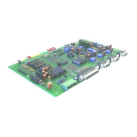
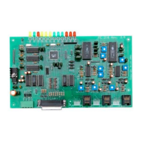
RC210 Repeater Controller
Assembly Manual
Hardware Version 3.3
 Loading...