5-7
5
NOTE: If the meter does not read as specified,
replace the spark plug cap.
PEAK VOLTAGE
NOTE: All of the peak voltage tests should be made
using the Fluke Model 77 Multimeter with Peak Volt-
age Reading Adapter. If any other type of tester is
used, readings may vary due to internal circuitry.
NOTE: The battery must be at full charge for these tests.
Primary/CDI
NOTE: The CDI is located under the seat near the
battery.
1. Set the meter selector to the DC Voltage position;
then disconnect the terminal and ground wires
from the coil.
2. Connect the red tester lead to the white/blue wire;
then connect the black tester lead to the black wire.
3. Crank the engine over using the electric starter.
4. The meter reading must be within specification.
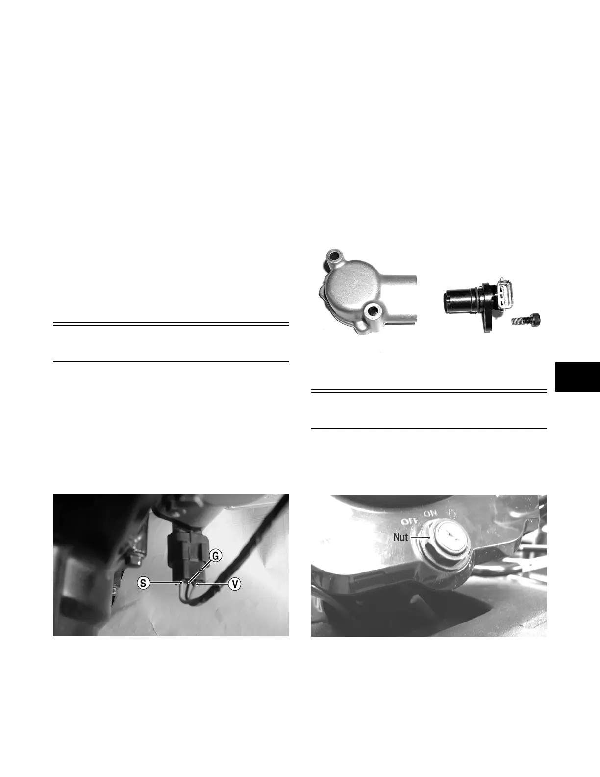
Speed Sensor
NOTE: Prior to testing the speed sensor, inspect the
three-wire connector on the speed sensor for con-
tamination, broken pins, and/or corrosion.
1. Set the meter selector to the DC Voltage position.
2. With appropriate needle adapters on the meter
leads, connect the red tester lead to the voltage
lead (V); then connect the black tester lead to the
ground lead (G).
CD885A
3. Turn the ignition switch to the ON position.
4. The meter must show 6-12 DC volts.
5. Leave the black tester lead connected; then con-
nect the red tester lead to the signal lead (S) pin.
6. Slowly move the ATV forward or backward; the
meter must show 0 and 6-12 DC volts alternately.
NOTE: If the sensor tests are within specifications,
the LCD gauge must be replaced (see Section 8).
To replace a speed sensor, use the following procedure.
1. Disconnect the three-wire connector from the
speed sensor harness or from the speed sensor;
then remove the Allen-head cap screw securing
the sensor to the sensor housing.
2. Remove the sensor from the sensor housing
accounting for an O-ring.
3. Install the new speed sensor into the housing with
new O-ring lightly coated with multi-purpose
grease; then secure the sensor with the Allen-head
cap screw (threads coated with blue Loctite #242).
Tighten securely.
CD071
Ignition Switch
The ignition switch harness connects to the switch with a
four-pin connector. To access the connector, remove the
ignition switch nut, remove the switch, and press the con-
nector release tab. Pull the connector from the switch.
CF272A
FOR ARCTIC CAT ATV DISCOUNT PARTS CALL 606-678-9623 OR 606-561-4983
www.mymowerparts.com
 Loading...