5-8
CF273A
VOLTAGE
NOTE: Perform this test on the harness connector.
1. Set the meter selector to the DC Voltage position.
2. Connect the red meter lead to either red wire; then
connect the black meter lead to ground.
3. Meter must show battery voltage.
NOTE: If the meter shows no battery voltage, trou-
bleshoot the battery or the main wiring harness.
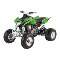
RESISTANCE
NOTE: Perform this test on the switch using the fol-
lowing procedure.
CF274A
1. Turn the ignition switch to the ON position.
2. Set the meter selector to the OHMS position.
3. Connect either tester lead to pin C; then connect
the other tester lead to pin D.
4. The meter must show less than 1 ohm.
5. Turn the ignition switch to the LIGHTS position.
6. Connect either tester lead to pin A; then connect
the other tester lead to pin B.
7. The meter must show less than 1 ohm.
8. Connect either tester lead to pin C; then connect
the other tester lead to pin D.
9. The meter must show less than 1 ohm.
10. With the switch in the OFF position, connect the
red tester lead and the black tester lead to each of
the remaining pins. The meter must show an open
circuit on all pins.
NOTE: If the meter shows more than 1 ohm of resis-
tance, replace the switch.
Handlebar Control
Switches
The connector is the yellow one next to the steering
post. To access the connector, the steering post cover
and the right-side fender splash shield must be
removed (see Section 8).
NOTE: These tests should be made on the top side
of the connector.
RESISTANCE (HI Beam)
1. Set the meter selector to the OHMS position.
2. Connect the red tester lead to the yellow wire; then
connect the black tester lead to the gray wire.
3. With the dimmer switch in the HI position, the
meter must show less than 1 ohm.
NOTE: If the meter shows more than 1 ohm of resis-
tance, replace the switch.
RESISTANCE (LO Beam)
1. Connect the red tester lead to the white wire; then
connect the black tester lead to the gray wire.
2. With the dimmer switch in the LO position, the
meter must show an open circuit.
NOTE: If the meter reads resistance, replace the
switch.
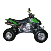
DIODE (Starter Button)
NOTE: If voltage is not as specified, check the con-
dition of the battery in the meter prior to replacing the
switch. A low battery will result in a low voltage read-
ing during a diode test.
1. Set the meter selector to the Diode position.
2. Connect the red tester lead to the orange/white
wire; then connect the black tester lead to the yel-
low/green wire.
3. With the starter button depressed, the meter must
show 0.5-0.7 DC volt.
4. With the starter button released, the meter must
show 0 DC volts.
FOR ARCTIC CAT ATV DISCOUNT PARTS CALL 606-678-9623 OR 606-561-4983
www.mymowerparts.com
 Loading...