5.7 Board Recovery
All Arduino® boards have a built-in bootloader which allows flashing the board via USB. In case a sketch locks up
the processor and the board is not reachable anymore via USB, it is possible to enter bootloader mode by double-
tapping the reset button right after power up.
6 Connector Pinouts
All the pins on J1 and J2 (excluding fins) are referenced to the V
DDIO_EXT
voltage which can be generated internally
or supplied externally.
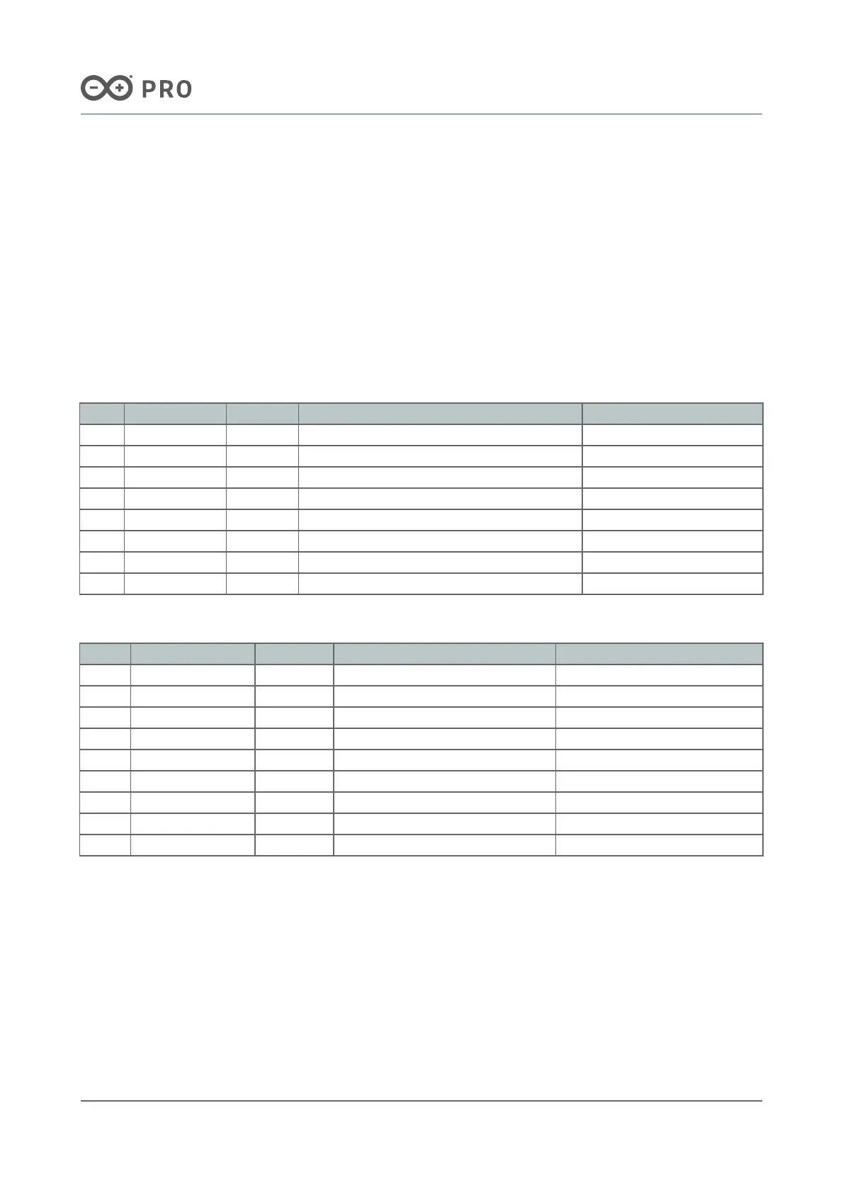
6.1 J1 Nicla Header A
Pin Function Type Description MKR Compatibility
1 LPIO0_EXT Digital Low Power IO Pin 0 A6
2 NC N/A N/A A5
3 CS Digital SPI Cable Select A4
4 COPI Digital SPI Controller Out / Peripheral In A3
5 CIPO Digital SPI Controller In / Peripheral Out A2
6 SCLK Digital SPI Clock A1
7 ADC2 Analog Analog Input 2 A0
8 ADC1 Analog Analog Input 1 AREF
6.2 J2 Nicla Header B
Pin Function Type Description MKR Compatibility
1 SDA Digital I2C Data Line SDA
2 SCL Digital I2C Clock SCL
3 LPIO1_EXT Digital Low Power IO Pin 1 RX
4 LPIO2_EXT Digital Low Power IO Pin 2 TX
5 LPIO3_EXT Digital Low Power IO Pin 3 RESET
6 GND Power Ground GND
7 VDDIO_EXT Digital Logic Level Reference 3.3 V
8 N/C N/A N/A VIN
9 VIN Digital Input Voltage 5V
Note: For further information on how Low Power I/Os work, check Nicla Family Form Factor documentation.

 Loading...


