6.3 J2 Fins
Between the main pins, there are smaller contacts (fins) that provide access to debugging capabilities. These test
points can easily be accessed by inserting the board in a double row 1.27 mm/50 mil pitch male header.
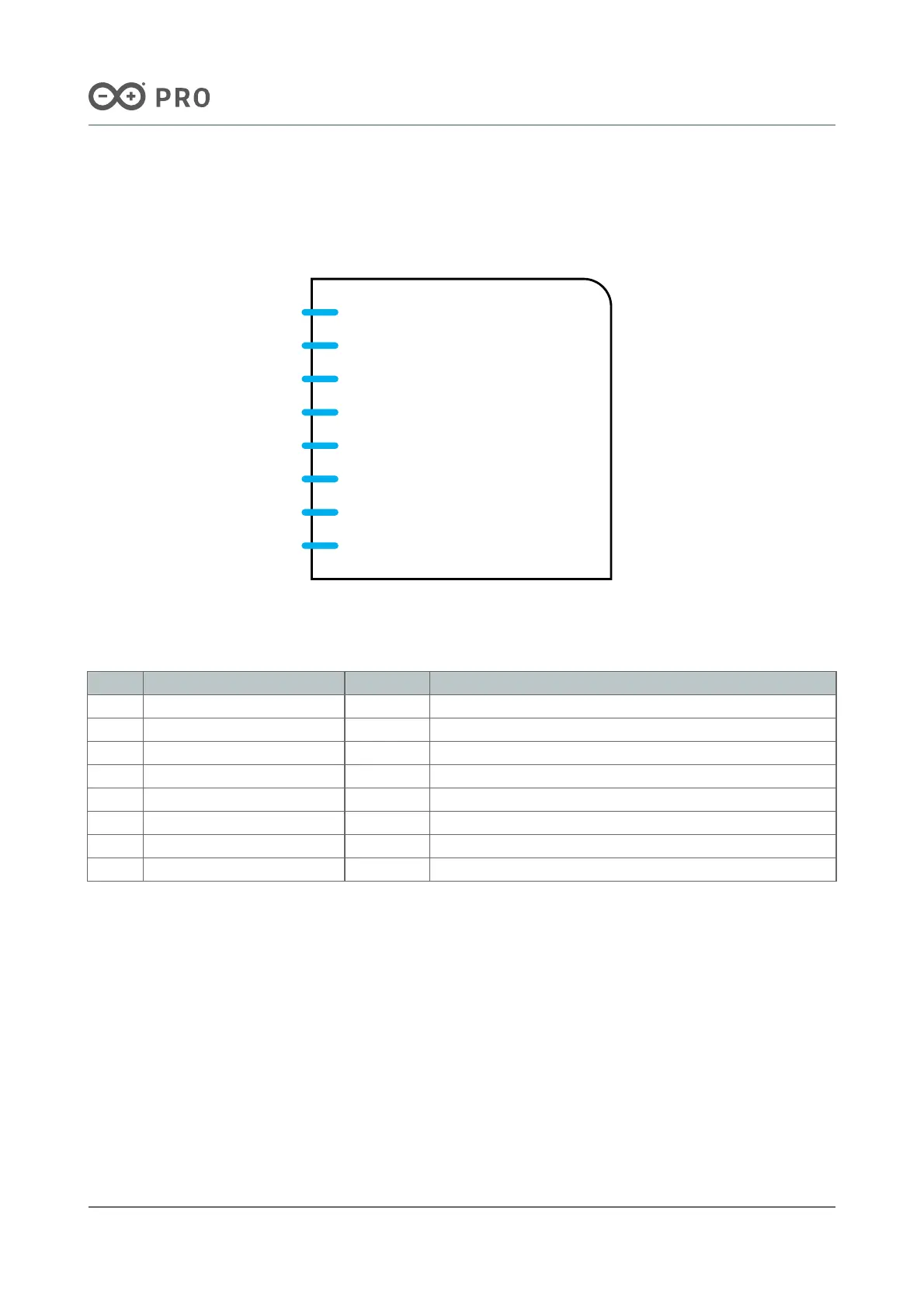
Nicla Family Bottom Fins
Pin Function Type Description
P1 BMI_SWDIO Digital BMI270 JTAG Serial Wire Debug Data
P2 BMI_SWDCLK Digital BMI270 JTAG Serial Wire Debug Clock
P3 ANNA_SWDIO Digital ANNA JTAG Serial Wire Debug Data
P4 ANNA_SWDCLK Digital ANNA JTAG Serial Wire Debug Clock
P5 RESET Digital Reset Pin
P6 SAMD11_SWDIO Digital SAMD11 JTAG Serial Wire Debug Data
P7 +1.8 V Power +1.8 V Voltage Rail
P8 SAMD11_SWDCLK Digital SAMD11 JTAG Serial Wire Debug Clock
Note: All JTAG logic levels operate at 1.8 V apart from the SAMD11 pins (P6 and P8) which are 3.3 V. All these JTAG
pins are 1.8 V only and don't scale with VDDIO.

 Loading...


