Arecont Vision SurroundVideo
®
Omni Installation Manual
Page | 13 support@arecontvision.com
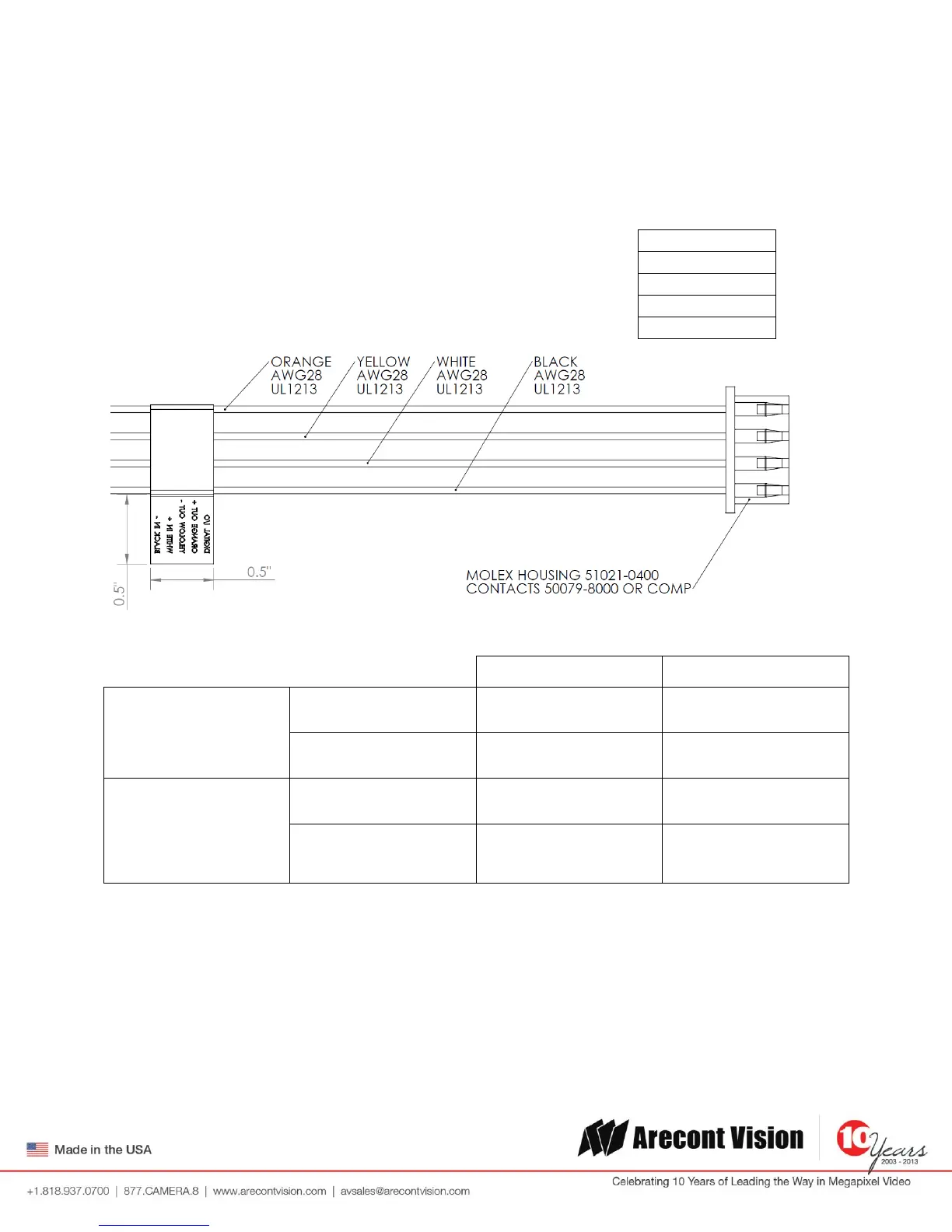
Digital Input and Output
Use 4 position connector inside camera housing to interface with Digital I/O.
Electrical Characteristics
Input Voltage (V)
(Measured between +
and – terminals)
Output Current (mA)
(Measured between +
and – terminals)
Applied Voltage Range :
0-80V
NOTE: Both the input and the output are electrically isolated from the rest of the camera’s electrical
circuitry via general-purpose photo couplers. The input is additionally protected with a serial 250 Ohm
resistor and a debouncing circuit. Duration of any input signal should be at least 5ms to comply with the
requirements of the debouncing circuit.
 Loading...