actual or scale drawings.
PRE-INSTALLATION
CODES
Check all applicable codes regulations and permits for installation requirements. Installation must
comply with utility regulations and local codes as well as those of the National Fire Protection
Associations 90A or 90B as applicable.
NOTE: Building of safety codes may require that exhaust fans be interlocked with the make-up air
unit. This requirement is satisfied with an optional ARES exhaust fan control relay assembly or
interface panel.
UNIT INSPECTION
Check unit for shipping damage. If damage is found, report it immediately to the carrier and file a
damage claim.
ROOF LOAD
Roof load-bearing capacity must be adequate to handle the operating weight of the make-up air unit. To
spread this load over additional roof joints and to support the unit above accumulated rainwater, 8"
mounted rails are frequently used.
Check roof loading and structure for support. Approximate operating weights are shown below.
BLOWER HOISTING OPERATION AVG. ROOF
WEIGHT WEIGHT LOADING
(Approx. lbs.) (lbs.) (PSF)
SE1/DE1 470 612 44.8
SC1/DC1 470 470 34.4
SE2/DE2 490 632 46.2
SC2/DC2 490 490 35.8
SC3 525 525 30.5
Hoisting weight includes crate. Operating weight includes water. Hoisting eyes are included to lift the
make-up air unit to the roof.
LOCATION
1. In a roof installation, units should be installed level on a roof curb, rails or roof stand (minimum 4"
high) to allow ventilation beneath the unit. Adequate space for a water drain connection is required
beneath the sump pan of the cooling section, which is also a 4" minimum.
2. If adequate air supply volume is provided, the unit may also be installed on a sidewall. Exact
location will depend upon building construction and the placement of ceiling registers and ducts.
These should be placed carefully to provide maximum distribution of make-up before it is drawn
into the exhaust systems.
3. Install the unit as close as possible to the supply register to minimize duct system resistance (total
external static pressure loss through the duct.)
4. Be sure the unit’s capacity is equivalent to the demands of the systems.
5. Duct velocity should not exceed 1500 FPM.
6. Do not install unit near plumbing vent pipes and exhaust stacks.
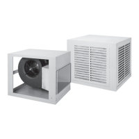
Make-up Air Blower Model SC1/SC2/SC3, SE1/SE2, DC1/DC2 and DE1/DE2
3
Tel: (800)-288-0892 • www.aresmakeupair.com