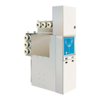
4 GHA l Switchgear extension and replacement of a panel
Remarks on this manual
Purpose
This Technical Manual is for information only. It describes
extension of an existing GHA double busbar switchgear, at choice to the ●
left or right-hand side.
replacement of a switchgear panel within a GHA double busbar switch- ●
gear.
The switchgear is not switched OFF completely for the individual assembly
descriptions, but the busbar systems remain in operation as far as possible.
For the sake of clarity, this manual does not include all information on the
various assembly descriptions in detail. Neither can it take every imaginable
instance of installation or operation into account.
This Technical Manual only provides a general overview of the work to be
performed in case of extension or replacement. In each case of extension, a
detailed switchgear-specific workflow must be prepared upon consultation with
the manufacturer. No extension or replacement must be performed on the basis
of this Manual alone.
Liability claims against the manufacturer cannot be based on this Techni-
cal Manual!
As our products are subject to continuous further development, we reserve the
right to make changes regarding standards, illustrations and technical data.
Reference documents
The following additional documents must be complied with:
sales agreement with the stipulations regarding the switchgear-specific ●
equipment and the legal details
the switchgear-specific circuit diagrams / documentation ●
Operating Manual GHA (no. AGS 531 44 ● 1-01)
Assembly Instructions GHA (no. AGS 531 44 ● 6-01)
the operating instructions for the devices installed in the switchgear ●
(e. g. IVIS, devices in low-voltage cabinet)
the assembly instructions of the manufacturer of the cable connection ●
systems to be connected to the switchgear
 Loading...