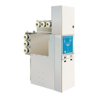
9GHA l Switchgear extension and replacement of a panel
Extension of an existing double 3
busbar switchgear system
Safety provisions3.1
Warning!
Comply with the safety provisions on page 6.
Warning!
Confusing the busbar system involves a risk of injury. The term
Busbar 1 (BB1) refers to the busbar arranged in the rear area of the
panel, and the term Busbar 2 (BB2) to the busbar arranged in the up-
per part of the panel.
During assembly, busbar 1 and busbar 2 must be identified clearly.
Earthed as well as energized busbars must be identified by the ap-
propriate warning and information signs.
Warning!
Risk of injuries. The mounted black end caps on the busbar ends
and the silicone sleeves of the busbar link are surge-proof and must
not be subjected to any mechanical stress.
Warning!
The initial position as shown, and the workflow described are in-
tended as examples only.
Before assembly is started, a complete description of the entire
workflow of a switchgear extension must be prepared and verified in
accordance with the local circumstances and conditions.
Important information3.2
The surge-proof black end caps and the silicone sleeves of the busbar ●
links are safe to touch due to an earthed external conductive surface.
Before positioning new panels, insert the busbar clamping contacts into ●
the busbar tubes of the left-hand panel concerned. Inserting the clamping
contacts after screw-fastening the panels would be very time-consuming.
The silicone link sleeves connecting the existing switchgear ● panel to the
extension panel may only be mounted on site.
 Loading...