15
3 Extension of an existing double busbar switchgear system
GHA l Switchgear extension and replacement of a panel
Extension on right-hand end of busbar3.5
1. Reroute all incoming and outgoing feeders to busbar 1 (Fig. 8).
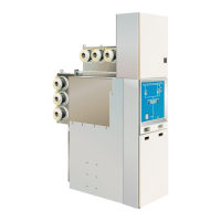
BB2 (top)
BB1 (rear)
Fig. 8
All incoming and outgoing feeder panels on busbar 1, busbar 2 earthed via the bus
coupler
Isolate busbar 2 from the power supply and earth it (the diagram shows 2.
busbar earthing via the bus coupler, Fig. 8; see also Operating Manual,
chap. 6.7).
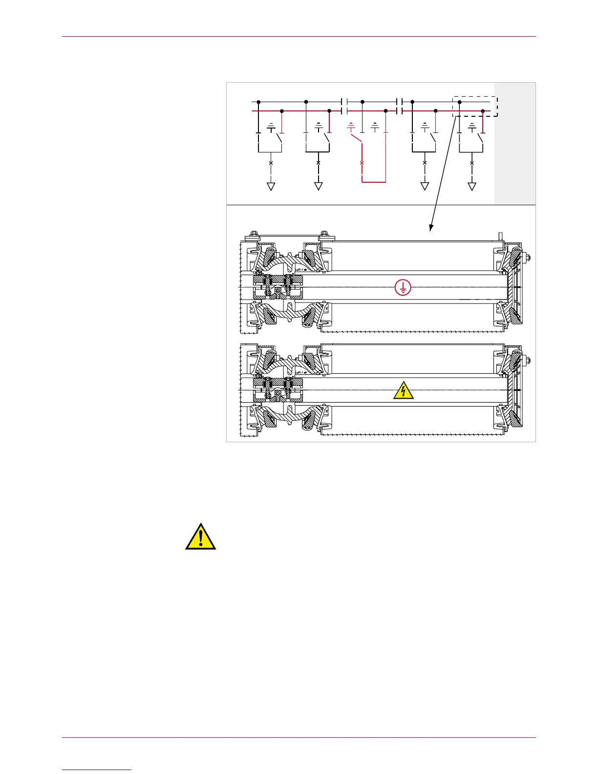
Warning!
Risk of injuries. The rear busbar (BB1) is in operation and the upper
busbar (BB2) earthed. Comply precisely with the safety provisions.
Remove right-hand gap cover and end plate and attach busbar identifica-3.
tions.
Remove right-hand metallic protective covers of busbars 1 and 2.4.
Remove right-hand end caps of busbar 2 (top). Treat new busbar clamp-5.
ing contacts in accordance with the Assembly Instructions and insert them
into BB2 of panel 9.
Clean and grease busbar bushings and the removed end caps, and re-6.
mount them.
BB2 is ready to operate again.
Preparation
BB1
BB2
 Loading...