16 GHA l Switchgear extension and replacement of a panel
3 Extension of an existing double busbar switchgear system
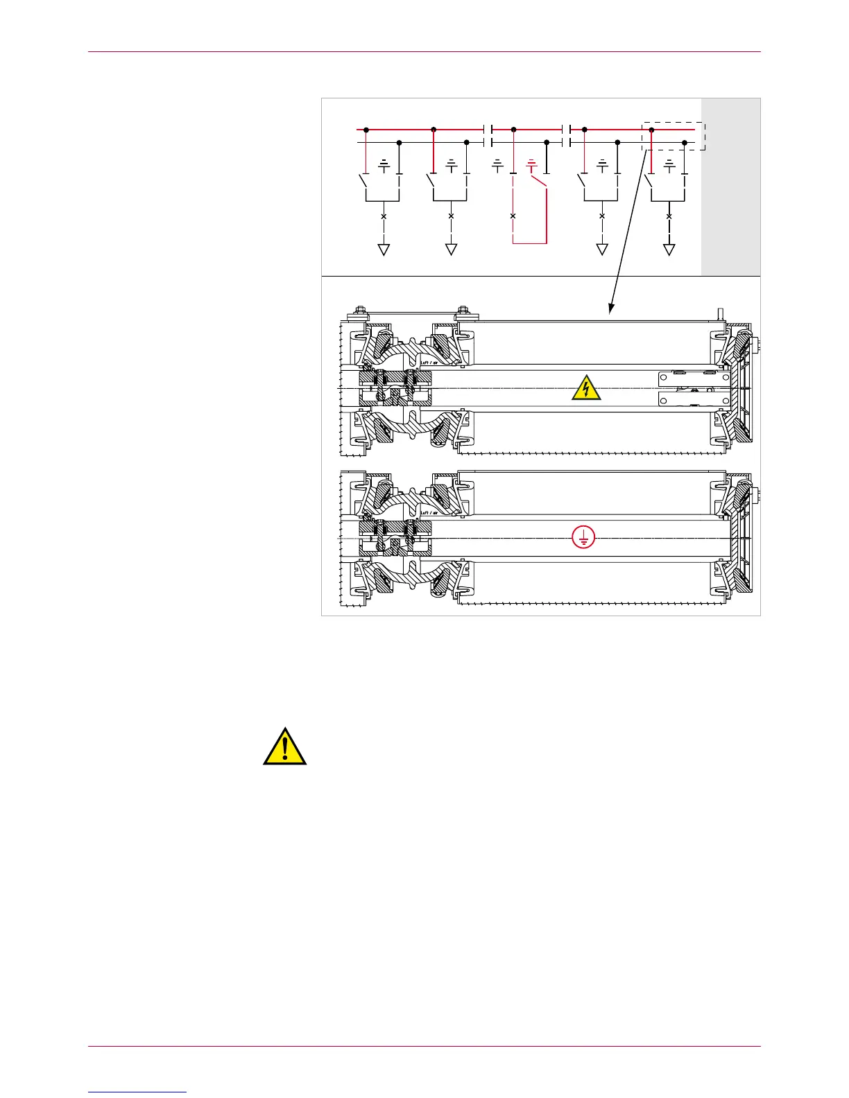
BB2 (top)
BB1 (rear)
Fig. 9
All incoming and outgoing feeder panels on busbar 2, busbar 1 earthed via the bus
coupler
Isolate busbar 1 from the power supply and earth it (the diagram shows 8.
busbar earthing via the bus coupler, Fig. 9; see also Operating Manual,
chap. 6.7).
Warning!
Risk of injuries. The upper busbar (BB2) is in operation and the rear
busbar (BB1) earthed. Comply precisely with all safety provisions
and check the busbar identifications.
Remove right-hand end caps of busbar 1 (rear). Clean and grease busbar 9.
bushings. Clean and grease silicone sleeves of link and mount them on the
new panel (see Assembly Instructions).
Clean the removed end caps of busbar 1 and reposition them on the 10.
new end panel (see also space assignment plan), unless they are already
provided.
Mount metallic protective cover to the new end of busbar 1.
Treat all contact surfaces in accordance with the Assembly Instructions.
Insert the new busbar clamping contacts into BB1 of panel 9.
BB1
BB2
 Loading...