17
3 Extension of an existing double busbar switchgear system
GHA l Switchgear extension and replacement of a panel
11. Position new panel on the base frame in accordance with the space as-
signment plan, align it and screw-fasten it to the adjacent panel and the
base frame (see Assembly Instructions).
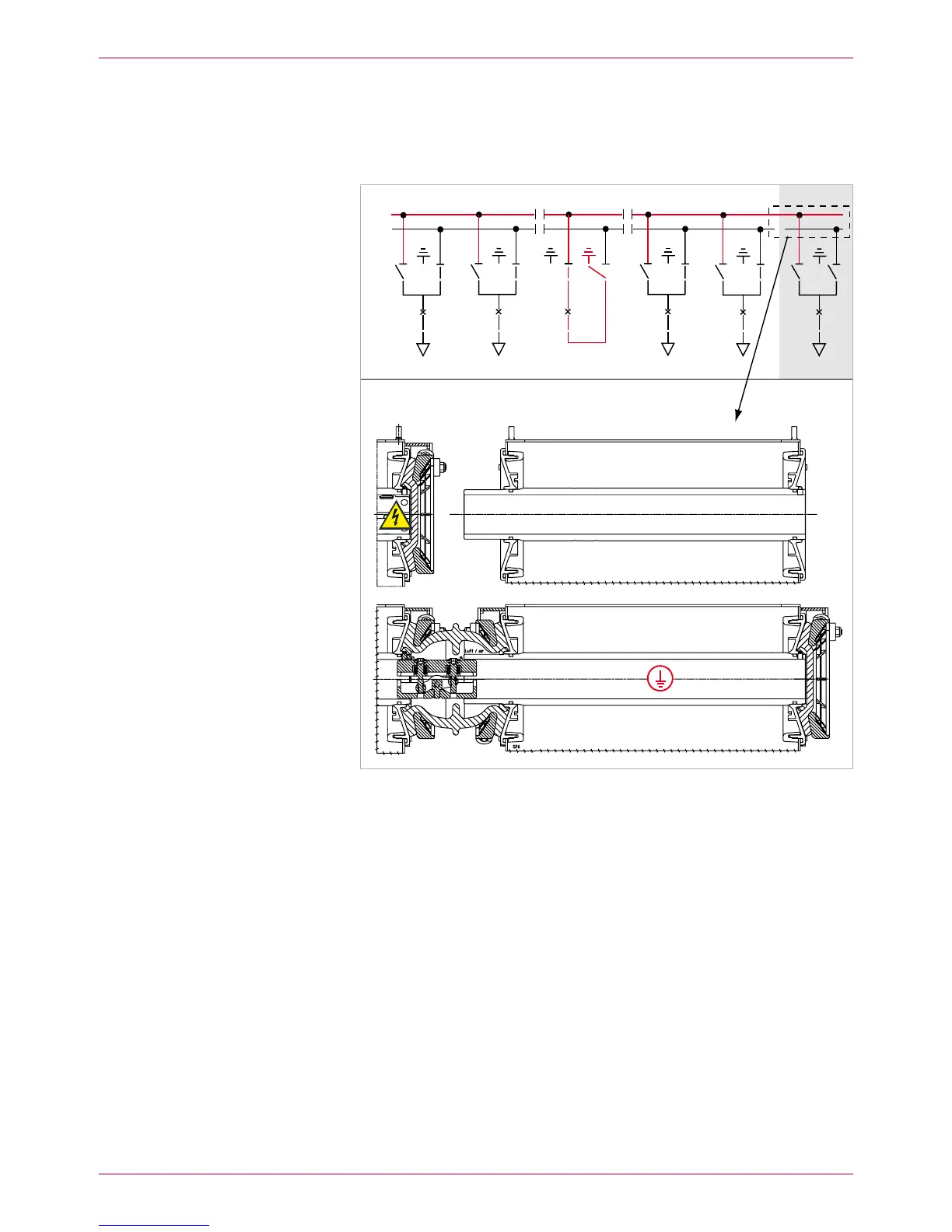
Mount busbar connection for busbar 1 completely with clamping contacts 12.
(see Assembly Instructions) (Fig. 10).
BB2 (top)
BB1 (rear)
Fig. 10
– New panel lined-up on the right-hand end
– Busbar 1 (rear) completely connected and ready to operate (protective cover on
busbar end not shown)
– Busbar 2 (top) not yet connected
If applicable, mount further panels in accordance with item 11. Mount both 13.
busbar systems BB1 and BB2 completely to the new panels (see Assem-
bly Instructions).
Line up new panel
BB1
BB2
 Loading...