18 GHA l Switchgear extension and replacement of a panel
3 Extension of an existing double busbar switchgear system
The further steps for assembly are to be performed in accordance with the 14.
Assembly Instructions:
connect the earth bars –
connect the low-voltage cables (ring lines, external customer cables –
Commission extension panels:
comply with Assembly Instructions (Chapter 10) –
check operating functions and interlocks of switching devices –
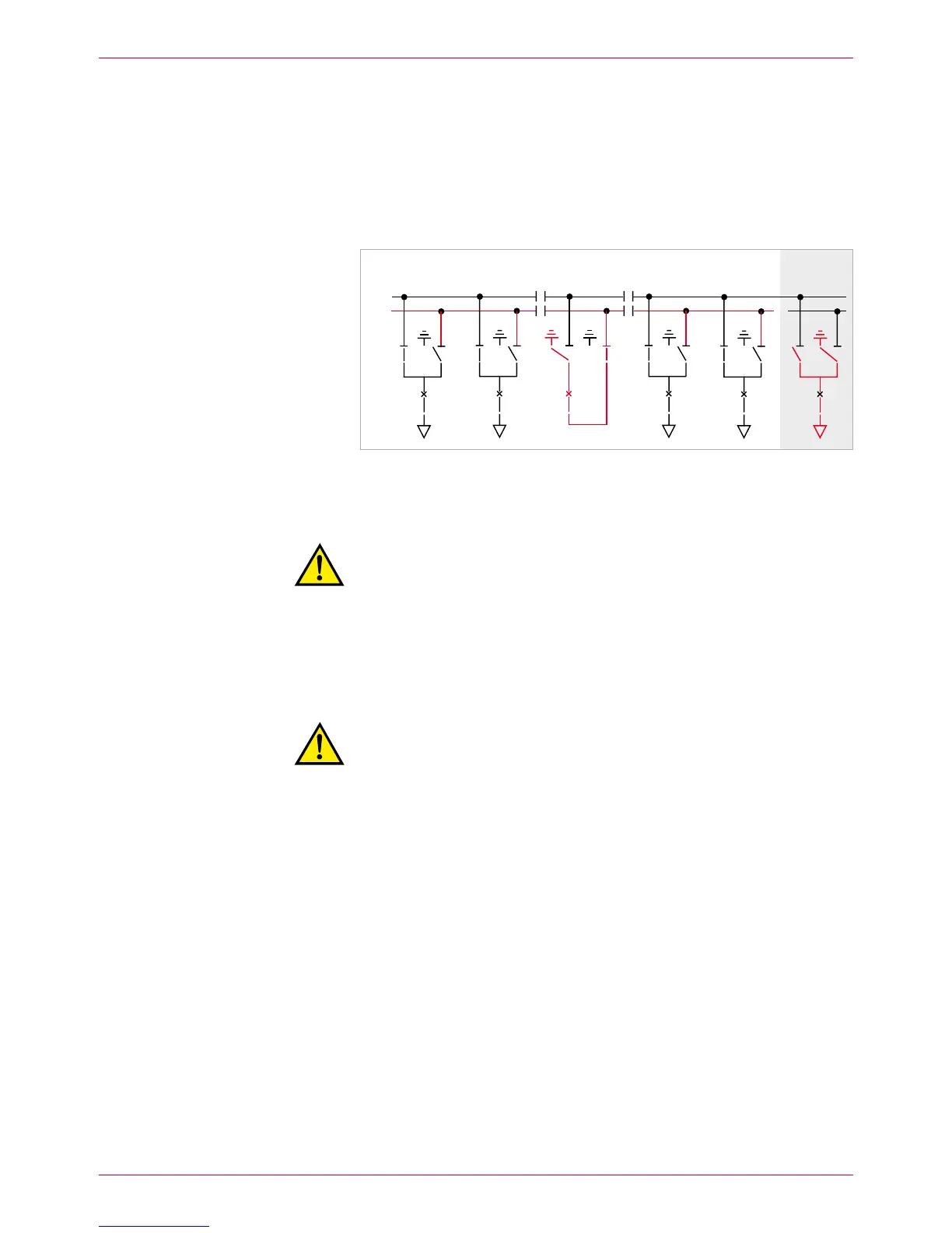
Set extension panels to „EARTHED“ position (Fig. 11).
Fig. 11
New panel earthed, all incoming and outgoing feeder panels on busbar 1, busbar 2
earthed via the bus coupler
Reroute panels to 15. BB1:
Warning!
For safety reasons, all persons must be located in front of the
switchgear during switching operations!
Cancel – BB1 earthing.
Switch bus coupler ON. –
Reroute panels to – BB1.
Isolate busbar 2 from the power supply and earth it (the diagram shows 16.
busbar earthing via the bus coupler, Fig. 11; see Operating Manual, chap.
6.7).
Warning!
Risk of injuries. Now, the rear busbar (BB1) is in operation and the
upper busbar (BB2) earthed. Comply precisely with all safety provi-
sions and check the busbar identifications.
Remove busbar end caps of busbar 2 and clean and grease all busbar 17.
bushings.
Clean and grease silicone link sleeve, insert it under preload and mount it
to the right on the panel.
BB1
BB2
 Loading...