19
3 Extension of an existing double busbar switchgear system
GHA l Switchgear extension and replacement of a panel
On the new panels, mount all upper busbar links of the 18. BB2 completely in
accordance with the Assembly Instructions (Fig. 12).
BB2 (top)
BB1 (rear)
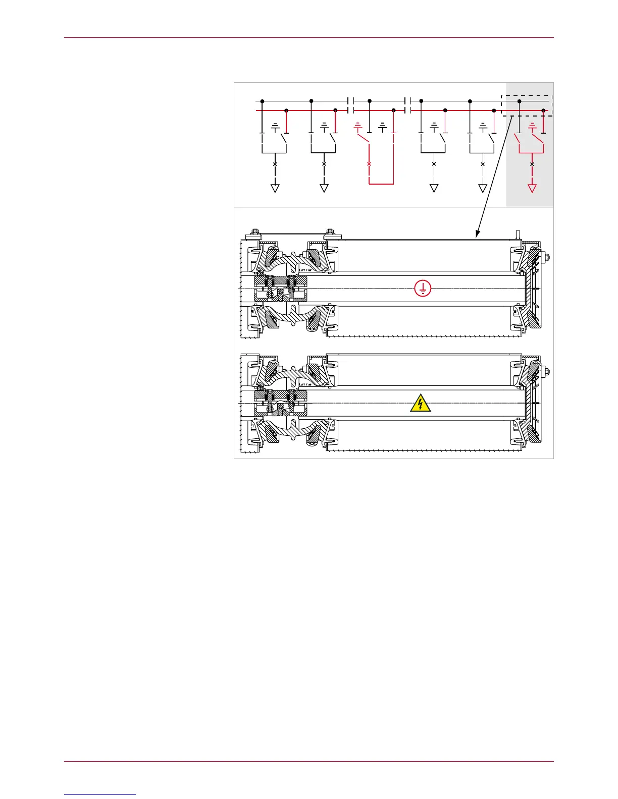
Fig. 12
New panel connected to the two busbars
Busbar 1 in operation
Busbar 2 still earthed, but ready to operate
(protective covers on busbar end not shown)
Remount the removed busbar end cap on the new end panel (unless 19.
already provided).
Mount metallic protective cover to the new busbar end.
All the other assembly steps are to be performed in accordance with the
Assembly Instructions:
attach right-hand end plate and gap cover. –
high-voltage terminals –
final steps –
BB1
BB2
 Loading...