Page 30
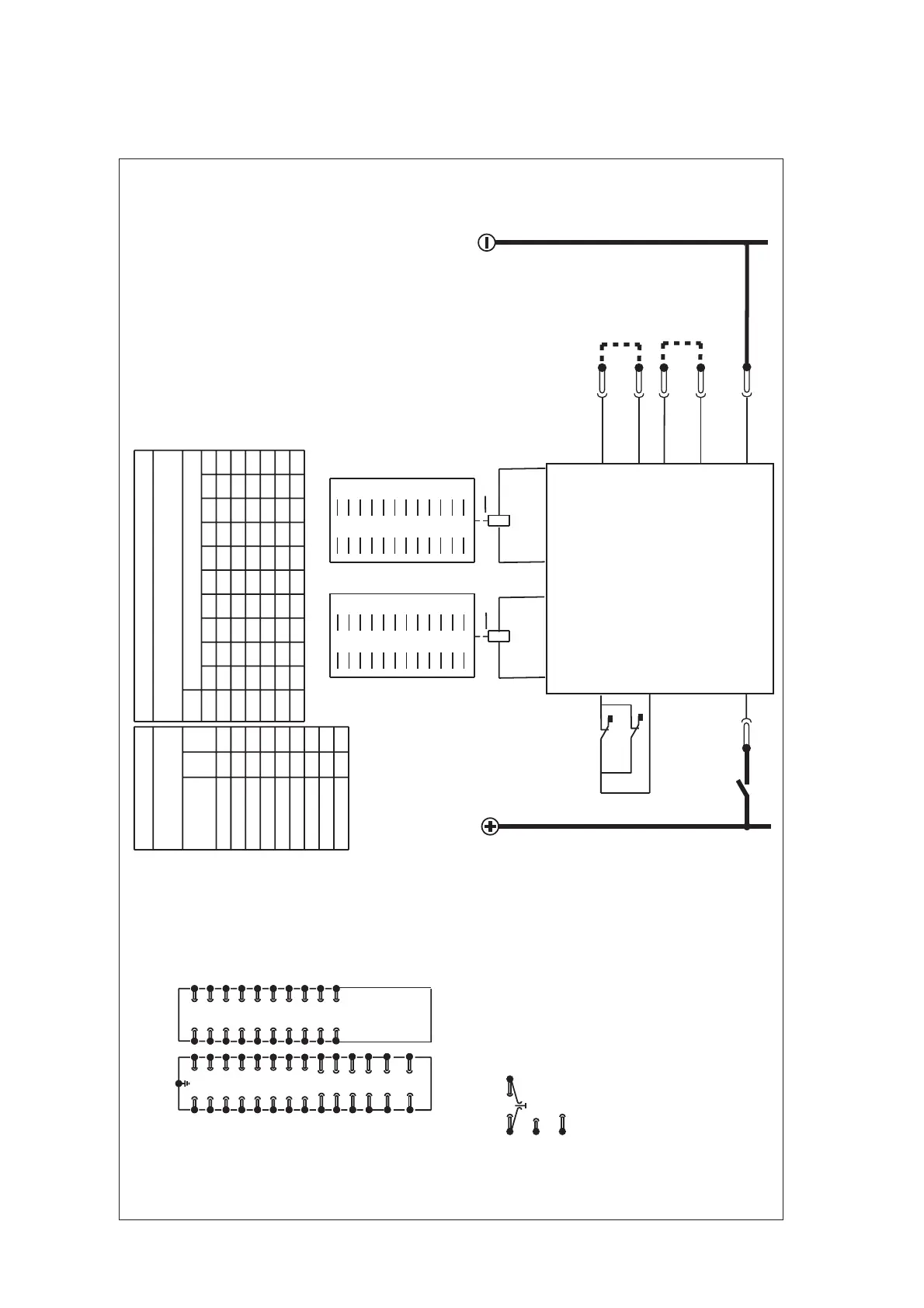
Figure 12: Typical application diagram MVAJ 203
Table 1
Table 2
Combinations of
output contacts
Output contacts to module terminals
Module terminals
Cont.
stack
L/h
stack
R/h
stack
Combination
(see Note 3)
Left hand
Contact description
M: Make
B: Break
Right hand
1 MMMM MMMM MM
2 B MMMMB MM MM
3 BBMMMBB MMM
4 BBBMMB B B MM
5 BBBB MBB B BM
29
31
33
35
1
3
5
7
37
39
41
43
9
11
13
15
45
47
17
19
2
4
30
32
34
36
38
40
6
8
10
12
42
44
14
16
46
48
18
20
L/h
R/h
2
4
6
8
10
12
14
16
18
20
B
1
3
5
7
9
11
13
15
17
19
A
30
32
34
36
38
40
42
44
46
48
B
29
31
33
35
37
39
41
43
45
47
A
Contact stacks viewed
from front
20M - 1 1
18M 2B 2 1
16M 4B 2 2
14M 6B 3 2
12M 8B 3 3
10M 10B 4 3
8M 12B 4 4
6M 14B 5 4
4M 16B 5 5
(OP)
(OP)
RL1
10
RL3
10
Vx
Case earth
Module terminal block
viewed from rear
Notes
CT shorting links make
before (b) and (c) disconnect
(a)
(b)
(c)
long terminals
short terminals break before (c)
2 Link in for high burden
Link out for low burden
3 Do not fit link
4 The numbers quoted for left hand and right hand stacks
in Table 1 are codenumbers used for cross references to
module terminals in Table 2.
1
12
3
4
5
6
7
8
9
10
11
12
13
14
15
16
17
18
19
20
21
22
23
24
25
26
27
28
29
30
31
32
33 34
35 36
37 38
39 40
41 42
43 44
45 46
47 48
23
21
24
22
See
Note 2
See
Note 3
28
27
PR
RL1-A
T4/T9
T3/T8
RL3-A
T27
T22
T24
T21
T23
T28
T20
T7
T2T1
ZJ0393
 Loading...


