Page 31
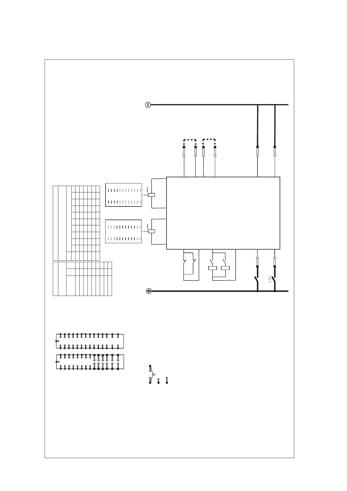
Figure 13: Typical application diagram MVAJ 204
Left hand
Right hand
Combinations of
output contacts
Table 1
(See Note 4)
Combination
Contact stacks
viewed from front
L/h
stack
R/h
stack
20M - 1 1
18M 2B 2 1
16M 4B 2 2
14M 6B 3 2
12M 8B 3 3
10M 10B 4 3
8M 12B 4 4
6M 14B 5 4
4M 16B 5 5
Table 2
Output contacts to module terminals
Module terminals
Cont.
stack
1MMMMMMMMMM
2BMMMMBMMMM
3BBMMMBBMMM
4BBBMMBBBMM
5BBBBMBBBBM
46
48
41
43
45
47
38
40
29
31
33
35
37
39
30
32
34
36
42
44
L/h
18
20
1
3
5
7
10
12
2
4
9
11
13
15
17
19
6
8
14
16
R/h
Contact description
M: Make
B: Break
2
4
6
8
10
12
14
16
18
20
B
1
3
5
7
9
11
13
15
17
19
A
30
32
34
36
38
40
42
44
46
48
B
29
31
33
35
37
39
41
43
45
47
A
CT shorting links make
before (b) and (c) disconnect
long terminals
2 Link in for high burden
Link out for low burden
Notes
1
(a)
(b)
(c)
3 Link for economising must be fitted.
4 The numbers quoted for left hand and right hand
stacks in Table 1 are code numbers used for
cross references to module terminals in Table 2.
short terminals break before (c)
Case earth
Module terminal block
viewed from rear
11
1
3
5
7
9
13
15
17
19
21
23
25
27
2
4
6
8
10
14
16
18
20
22
24
26
28
12
39
29
31
33
35
37
41
43
45
30
32
34
36
38
42
44
46
40
47
48
49
50
51
52
53
54
55
56
(OP)
(OP)
RL1
20
RL3
20
Vx
23
21
24
22
See
Note 2
See
Note 3
28
27
PR
RL1-A
T4/T9
T3/T8
RL3-A
T27
T22
T24
T21
T23
T28
T20
T7
T2T1
ZJ0393
26
T26
25
Reset
T25
RL1-B
T5/T6
T10/T11
RL3-B
RL1
RL3
(Reset coils)
 Loading...


