Do you have a question about the Argo WALL 18000 UE and is the answer not in the manual?
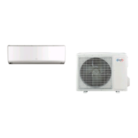
Summary of the indoor unit model and its components.
Summary of the outdoor unit model and its components.
Identification of the remote controller model used with the unit.
Detailed technical specifications for the unit, including capacity, power, and dimensions.
Graphical representation of unit performance under varying conditions.
How cooling/heating capacity changes with temperature.
Data sheet for cooling and heating performance at rated frequency.
Graphical data showing noise levels at different operating speeds.
Physical dimensions and mounting details for the indoor unit.
Physical dimensions and mounting details for the outdoor unit.
Electrical wiring schematic for the unit's internal connections.
Layout and component identification for the Printed Circuit Boards.
Overview of the remote controller buttons and their functions.
Detailed explanation of the unit's operating modes and special functions.
Conditions for starting and finishing the defrosting cycle.
Explanation of operational logic for compressor, fans, and valves.
Safeguards against voltage issues, communication failures, and module overheating.
Protection against compressor overload and phase current issues.
Procedures for starting estimation and compressor frequency reduction.
Management of compressor frequency and power turn-off conditions.
Important safety, electrical, installation, and refrigerant precautions.
Visual guide showing required clearances for unit placement.
Step-by-step guide for the installation process.
Checklist of components to verify before installation.
Guidelines for choosing optimal indoor and outdoor unit placement.
Safety and technical requirements for electrical hookup.
Detailed steps for mounting and connecting the indoor unit.
Detailed steps for mounting and connecting the outdoor unit.
Procedure for removing air from the refrigerant system.
Methods for detecting refrigerant leaks in the system.
Final checks to ensure proper installation before operation.
Steps to verify unit functionality and client acceptance.
Table of error codes, their meanings, causes, and countermeasures.
Diagnostic steps for core system faults like sensor, motor, and protection issues.
Troubleshooting issues related to refrigerant capacity charging.
Diagnosing IPM protection, desynchronizing, and overcurrent issues.
Addressing high temperature and overload protection faults.
Resolving issues when the unit fails to start correctly.
Troubleshooting overload and high discharge temperature malfunctions.
Resolving issues related to Power Factor Correction malfunction.
Diagnosing and fixing communication errors between units.
Troubleshooting compressor overload protection.
Resolving malfunctions caused by overcurrent protection.
Addressing problems when the air conditioner fails to start.
Resolving problems with poor cooling or heating performance.
Troubleshooting issues with the horizontal louver's movement.
Identifying and fixing causes of water leaks from the unit.
Diagnosing and resolving unusual noises or vibrations.
Illustrated breakdown and part numbers for the indoor unit assembly.
Illustrated breakdown and part numbers for the outdoor unit assembly.
Step-by-step instructions for safely disassembling the indoor unit.
Step-by-step instructions for safely disassembling the outdoor unit.
Conversion table for temperature units.
Guidelines for pipe lengths, refrigerant charging, and diameters.
Instructions for proper pipe expansion to prevent leaks.
Tables correlating temperature sensor resistance to actual temperature.
| Brand | Argo |
|---|---|
| Model | WALL 18000 UE |
| Category | Air Conditioner |
| Language | English |