pressure. Speed is controlled by the amount of
switch trigger depression.
WARNING: Do not operate for long
periods at low speed because excess
heat will be produced internally.
Fig.C
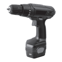
2. SWITCH LOCK (See Fig. D)
The switch trigger can be locked in the OFF
position. This helps to reduce the possibility of
accidental starting when not in use. To lock the
switch trigger, place the rotation control in the
center position.
Fig.D
OFF position
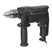
3. REVERSIBLE (See Fig.E1, E2)
For drilling and screw driving use forward rotation
marked “ ” (lever is moved to the left). Only
use reverse rotation marked “ ” (lever is
moved to the right) to remove screws or release a
jammed drill bit.
WARNING: Never change the direction
of rotation when the chuck is rotating,
wait until it has stopped!
Fig.E2
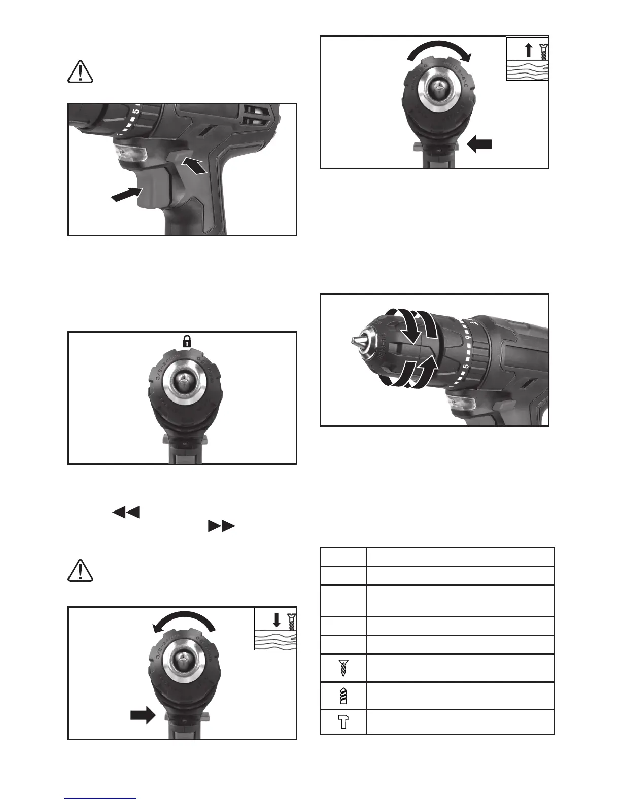
4. CHUCK ADJUSTMENT (See Fig. F)
To open the chuck jaws rotate the front section of
the chuck. Insert the drill bit between the chuck
jaws and rotate the front section in the opposite
direction. Ensure the drill bit is in the center of the
chuck jaws. Finally, rmly rotate the front chuck
section in the opposite directions. Your drill bit is
now clamped in the chuck.
Fig.F
5. TORQUE ADJUSTMENT (See Fig. G)
(Screw driving force of your drill driver)
The torque is adjusted by rotating the torque
adjustment ring (2). The torque is greater when
the torque adjustment ring is set on a higher
setting. The torque is less when the torque
adjustment ring is set on a lower setting.
Make the setting as follows:
1 - 4 for driving small screws
5 - 9 for driving screws into soft material
10 - 14
for driving screws into soft and hard
material
15 - 20 for driving screws into hard wood
21 for driving larger screws
for screwdriving
for heavy drilling
for drilling in masonry and concrete
Fig.E1
 Loading...