FOR MODELS: JGW, JGR AND JGJ SECTION 4 - LUBRICATION AND VENTING
1/01 PAGE 4 - 23
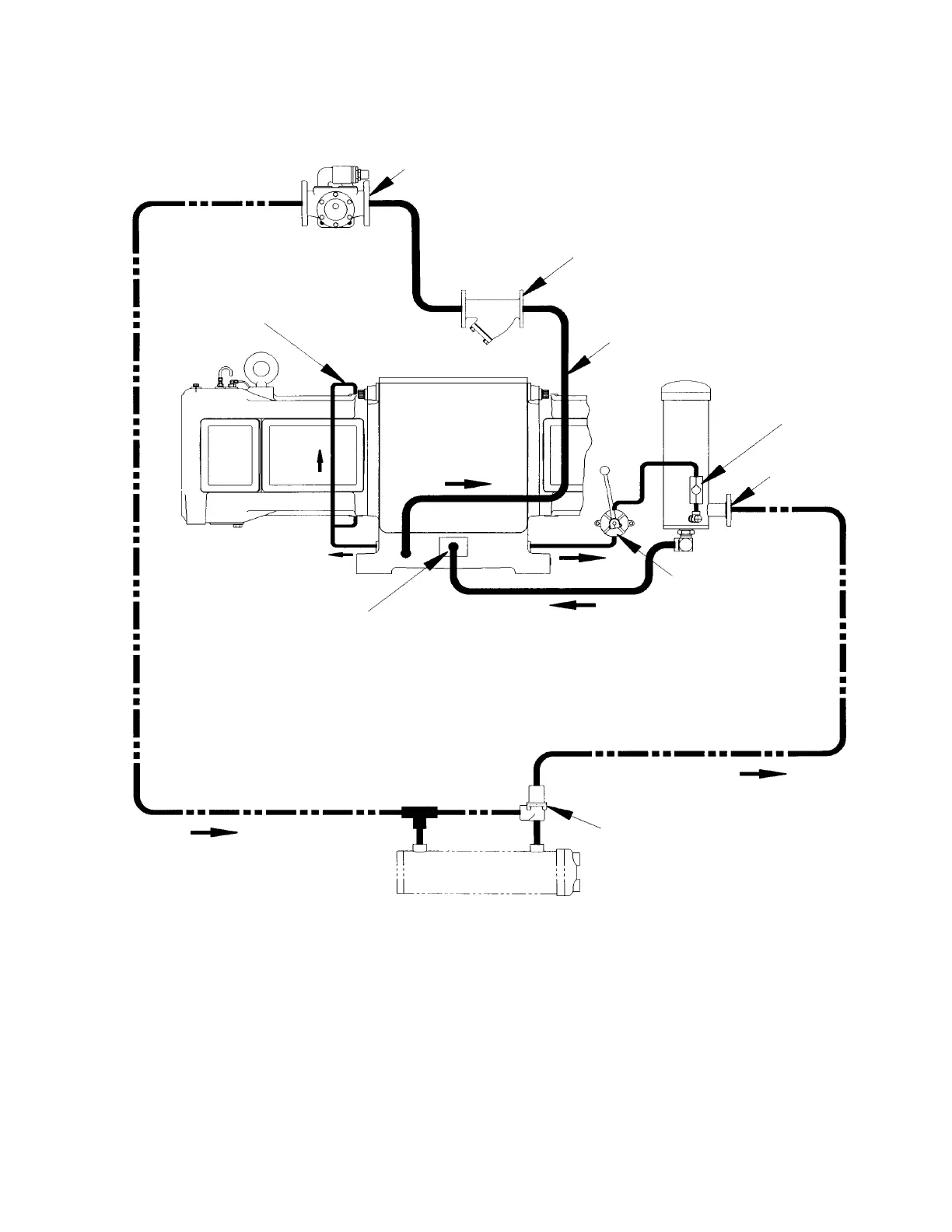
FIGURE 4-10: LUBE OIL SYSTEM SCHEMATIC - TYPICAL
Lube Oil Pump
Piping By Ariel
Lube Oil
Strainer
Hand - Priming
Pump
Check
Valve
Thermostatic
Control Valve
Oil Tubing From Frame
Gallery to Top and Bot-
tom of Guide to Lubri-
cate Crosshead
Lube Oil Inlet to Cast-In Oil Gallery. Oil
flows to the Crankshaft Main Bearings
and thru Drilled Holes in the Crankshaft
to Connecting Rod Bearings. From
there, thru Drilled Holes in the Connect-
ing Rods to the Crosshead Pins and
Bearings.
Lube Oil Cooler
Customer Lines
Filter
Inlet
Customer Lines
A
B
C
 Loading...