4 - 8
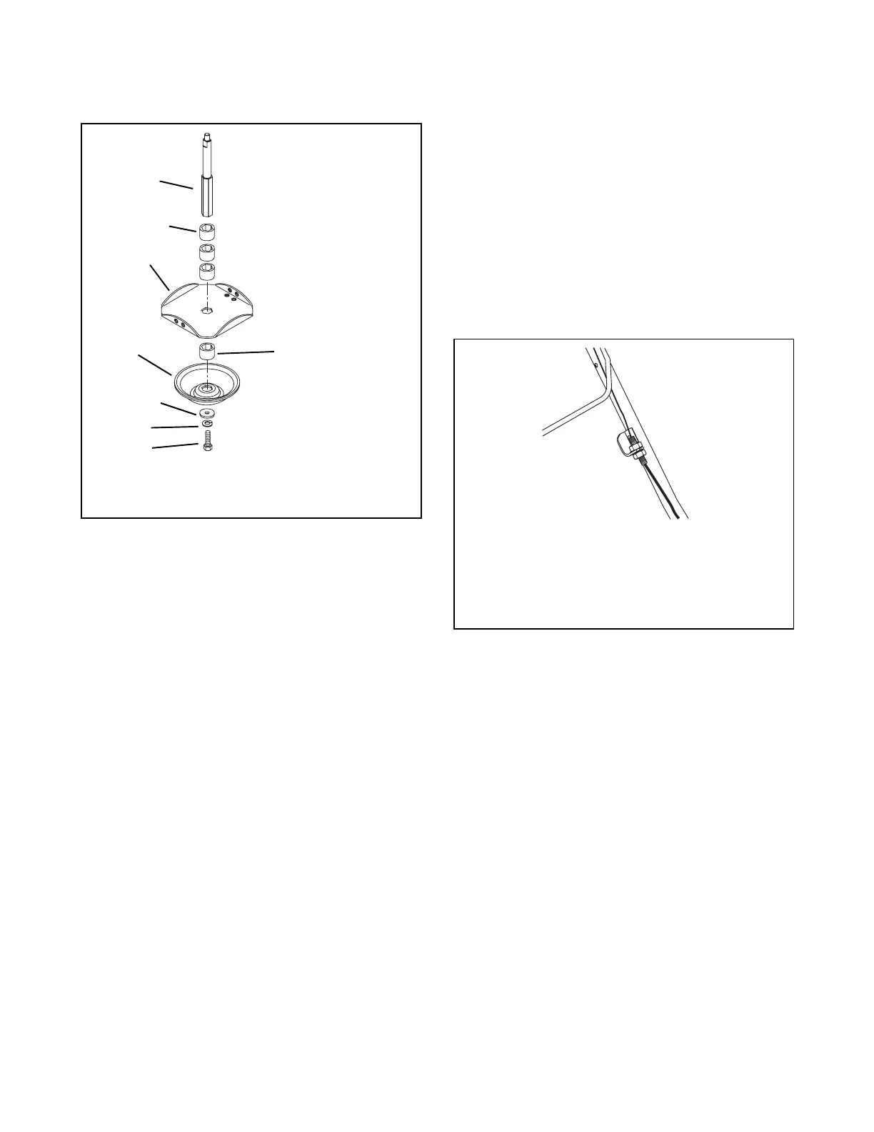
above the cutter disk. For example, if you place two
spacers under the cutter disk, the other two spacers
must be in place above the cutter disk.
NOTE:
There must always be at least one spacer
between the cutter disk and the height guide.
1. Raise the cutter head off the ground.
2. Loosen and remove capscrew, lock washer and
washer.
3. Remove height guide and bottom spacer.
4. Remove cutter disk and any of the remaining
spacers required to achieve the desired cutting
height.
5. Reinstall the cutter disk.
6. Reinstall the spacers required to achieve the
desired cutting height.
7. Reinstall height guide on the hex shaft.
NOTE:
Be sure the hex shaft and the hex hole in the
height guide are correctly aligned.
8. Reinstall washer, lock washer and capscrew.
Tighten securely.
NOTE:
The minimum cutting height may be lowered to
1-3/16" by using one spacer below the cutter disk and
installing the cutter disk upside down on the hex shaft.
4.7 CONTROL BAIL TRAVEL
ADJUSTMENT
Control bail must disengage trimmer head as control is
released. There should be a slight amount of slack in
the control cable wire when bail is fully released. If the
trimmer head does not disengage completely when the
control bail is released, increase the amount of slack in
the control cable wire as follows:
1. Loosen the bottom cable nut.
2. Push the cable conduit upward toward the control
bail.
3. Tighten the upper cable nut onto the mounting
bracket to lock the conduit in place.
4. Turn nuts against mount to lock in position.
OX0090
Figure 5
1. Hex Shaft
2. Spacers
3. Cutter Disc
4. Height Guide
5. Washer
6. Lock Washer
7. Cap Screw
1 spacer = 2"
2 spacers = 2-3/4"
3 spacers = 3-5/8"
4 spacers = 4-3/8"
1
2
3
4
5
6
7
OX0120
Figure 6
1. Control Cable
2. Control Cable Wire
3. Control Ball
4. Handlebar
5. Cable Nuts
6. Cable Conduit


 To Next Page