J
jdiazAug 2, 2025
What to do if my Ariens Gravely 915 ZT EZT Lawn Mower will not crank?
- RRyan OwensAug 2, 2025
If your Ariens Lawn Mower will not crank, charge or replace the battery.
What to do if my Ariens Gravely 915 ZT EZT Lawn Mower will not crank?
If your Ariens Lawn Mower will not crank, charge or replace the battery.
| Brand | Ariens |
|---|---|
| Model | Gravely 915 ZT EZT |
| Category | Lawn Mower |
| Language | English |
Details the manual's purpose, intended audience, and reading recommendations.
Guides on ordering parts and making inquiries using unit serial numbers.
Warns against using non-genuine parts and their potential consequences.
Outlines different types of technical information provided by the manufacturer.
Explains safety alert symbols and their importance for user safety.
Lists general safety precautions related to the equipment itself.
Provides comprehensive safety rules for operating the unit and general precautions.
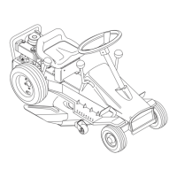
Identifies and illustrates the main controls and features of the unit.
Instructions for moving the unit when the engine is off or not driving.
Safe procedures for adding fuel to the unit's tank.
Details lubrication points, intervals, and types of lubricant.
Explains how to engage and disengage the front axle locking mechanism.
Step-by-step guide for detaching the mower deck from the unit.
Procedures for adjusting deck level and cutting pitch for optimal performance.
Guidance on setting the anti-scalp rollers to prevent lawn damage.
Steps to ensure the hydrostatic transmission is in neutral.
Instructions for aligning steering to ensure straight unit travel.
Procedure for adjusting the parking brake linkage and function.
A troubleshooting chart for common engine problems and their solutions.
How to properly check the engine oil level before operation.
Step-by-step guide for draining and refilling engine oil.
Detailed steps for removing the engine from the unit.
Step-by-step guide for installing the engine onto the unit.
Procedure for removing and installing the PTO belt.
Steps for safely removing and installing mower blades.
Guidelines for sharpening mower blades and when to replace them.
Troubleshooting chart for hydro transmission issues.
Specifies recommended fluid types for the Hydro-Gear transaxle.
Detailed instructions for removing the Hydro-Gear transmission.
Procedure for replacing the hydrostatic drive belt.
Overview of the manual mower deck lift system.
Steps for removing the mower deck lift system components.
How steering controls operate and their removal procedure.
Steps to adjust steering lever height for specific serial numbers.
Troubleshooting guide for common fuel system problems.
Explanation of the impulse style fuel pump operation.
Procedures for addressing fuel contamination issues.
Information on the material composition of the fuel tank.
Steps to safely remove the fuel tank from the unit.
Lists specialized tools and supplies for electrical repair.
Explains basic electrical measurements and meter usage.
Covers battery maintenance, removal, installation, and charging procedures.
Guides on testing normally open and normally closed switches.
Explains the principles and operation of solenoids and relays.
Overview of simple lighting circuits and troubleshooting.
Function, testing, and replacement of electrical fuses.
Explains the function and testing of diodes and rectifiers.
Details the operation and function of the electric clutch.
Tests for the safety interlock system for units above serial number 10,000.
Diagram illustrating the electrical system for serial numbers above 10,000.
Wiring diagrams for serial numbers above 10,000.
Diagrams showing electrical component continuity states.
Tests for the safety interlock system for serial numbers 5,000-9,999.
Diagram of the electrical system for serial numbers 5,000-9,999.
Wiring diagrams for serial numbers 5,000-9,999.
Diagrams showing electrical component continuity states.
Tests for the safety interlock system for serial numbers below 5,000.
Diagram of the electrical system for serial numbers below 5,000.
Wiring diagrams for serial numbers below 5,000.
Diagrams showing electrical component continuity states.
Steps to remove and replace the mower spindle assemblies.