A
agrahamAug 4, 2025
What to do if my Ariens Snow Blower will not crank?
- KkatherinesteinAug 5, 2025
If your Ariens Snow Blower will not crank, the suggested solution is to charge the battery or replace it.
What to do if my Ariens Snow Blower will not crank?
If your Ariens Snow Blower will not crank, the suggested solution is to charge the battery or replace it.
Provides complete instructions for service, maintenance, disassembly, repair, and installation of mechanical components.
Details on ordering publications, replacement parts, and making service inquiries using model and serial numbers.
Explains warranty registration card process and its importance for activating warranty coverage.
Warns against using non-Ariens parts, citing potential performance, durability, safety issues, and warranty voidance.
Ariens reserves rights to change products without notice; manual specifications were current at printing.
Describes various communication types used to inform dealers about product information and updates.
Explains symbols used to highlight important safety precautions and their meaning: Attention, Personal Safety, Alertness, Obey.
Defines DANGER, WARNING, and CAUTION signal words used to indicate hazard severity and potential consequences.
Defines NOTE for general information and IMPORTANT for specific procedures to prevent unit damage.
Advises following safe working precautions, understanding safety messages, and being alert to unsafe conditions.
Emphasizes providing this manual and safety training to anyone operating the unit other than the original purchaser.
Highlights importance of preparation, clean work area, and gathering tools/parts before starting service repairs.
Details proper positioning for service, including stable support, flat surface, and securing the unit.
Provides guidelines for cleaning, avoiding water on bearings, and proper storage practices.
Covers walk-around inspection, work area, unit operation, hazardous slopes, child safety, personal safety, controls, and maintenance guidelines.
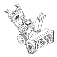
Identifies and illustrates key controls and features of the snow-thro unit, including levers, switches, and components.
Details procedures for placing the unit in Belt Service Position and On-End Service Position for maintenance.
Provides essential safety warnings and instructions for safely refueling the snow-thro unit.
Explains the function and importance of the fuel shut-off valve for transport, storage, and servicing.
Provides guidance on lubrication points, grease type, and frequency for unit maintenance.
Details lubricant type, level check, and maintenance for the auger gearcase.
Covers engine cooling requirements, engine oil checks, and procedures for changing engine oil.
Provides safety warnings and instructions for replacing the traction drive belt.
Offers safety warnings and steps for replacing the attachment drive belt, including adjustment.
Explains the purpose of shear bolts and provides instructions for their replacement.
Specifies the recommended maximum tire pressure for the unit.
Covers adjustments for discharge chute deflector, runners, scraper blade, and chute crank.
Details removal and replacement procedures for the upper handlebar panel and key switch.
Provides instructions for removing and replacing the lower handlebar.
Guides on removing and replacing the attachment clutch handle and related components.
Explains how to adjust the attachment clutch for proper engagement and slack.
Details removal and replacement of the wheel drive clutch lever and traction rod.
Provides instructions for removing and replacing the clutch yoke and fork assembly.
Offers a chart of common engine problems, their possible causes, and corrective actions.
Outlines the steps required to safely remove the engine from the unit.
Provides instructions for installing the engine, including connections and alignment.
Details the removal and servicing of the differential, lockout hub, and axles.
Explains how to remove and service axle bearings.
Covers removal and inspection of the pinion shaft, sprocket, and related bushings.
Provides steps for removing and servicing the reduction shaft and sprocket.
Details procedures for servicing the hex shaft, including bearing and sprocket removal.
Explains how to remove a link from the drive chain and the chain from the sprocket.
Guides on adjusting drive chain tension and checking interlock mechanisms.
Provides steps for replacing the friction wheel and adjusting the traction drive clutch.
Details removal and replacement of the friction wheel carrier and its components.
Covers removal and replacement of the drive plate spindle housing and related parts.
Outlines the procedure for removing the auger/impeller assembly from the housing.
Explains scraper blade adjustability for wear compensation and proper positioning.
Details the purpose of shear bolts and provides instructions for their replacement.
Provides instructions for removing and securing the discharge chute.
Guides on installing a new deflector cable and adjusting the deflector position.
Explains runner adjustment based on surface type for optimal scraper blade clearance.
Details removal, assembly, and lubrication of the cast iron gear case and worm gear.
Covers removal, bushing replacement, and lubrication of the aluminum gear case.
| Brand | Ariens |
|---|---|
| Model | ST 1132 LE |
| Category | Snow Blower |
| Language | English |