Do you have a question about the Arista 7000 Series and is the answer not in the manual?
Lists supported Arista Networks Data Center Switches.
Process for checking shipments and verifying contents against packing list.
Overview of the main tasks required for switch installation.
Guidance on safety information and translated warnings.
Methods for contacting Arista support for technical assistance.
Lists physical and operational specifications for Arista Data Center switches.
Criteria for choosing a suitable location for switch installation.
Steps to change the airflow direction of fans and power supplies.
Lists necessary tools and parts for installing the switch.
Guidelines to prevent damage from static electricity during handling.
Procedure for mounting the switch in a two-post rack.
Procedure for mounting the switch in a four-post rack.
Instructions for connecting the switch to the data center ground.
Guidelines for connecting power cables to the switch.
Details on connecting console, USB, and Ethernet management ports.
Description of LEDs on the front panel of the switch.
Status LEDs for fan and power supply modules on the rear panel.
Lists parts included in the accessory kit for rack mounting.
Lists cables provided with the switch accessory kit.
Explains port grouping for flexible Ethernet speed configuration.
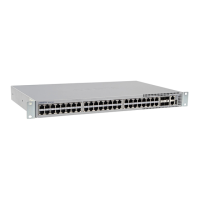
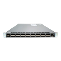
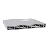
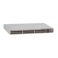
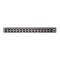
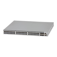
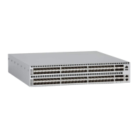
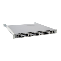
Displays the front panel layout of various switch models.