Do you have a question about the Arista DCS-7010T-48 and is the answer not in the manual?
Defines the intended audience and scope of the guide for installing Arista Networks Data Center Switches.
Provides instructions for inspecting the switch upon arrival, checking for damage, and verifying contents against the packing list.
Outlines the sequence of tasks required for installing and using the Arista Networks Data Center Switch.
Refers to Arista Networks document for safety information and translated safety warnings.
Details how customers can obtain technical support via email or the Arista Networks support web portal.
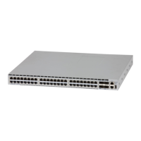
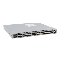
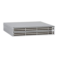
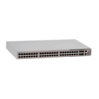
Provides detailed specifications for the 7010X 1RU Series switches, including dimensions, weight, operational, and power input.
Criteria for selecting an installation site, focusing on temperature, ventilation, and airflow orientation.
Lists the necessary tools and equipment required for the installation of the switch.
Guidelines to prevent ESD damage during installation and servicing, emphasizing static-free environments and protective measures.
Instructions for mounting the switch in a two-post or four-post rack using provided brackets.
Details on preparing the switch for placement on a flat surface using rubber pads.
Explains the importance of grounding the switch to the data center ground and shows grounding points.
Details the installation requirements for connecting AC and DC power supplies to the switch.
Describes connecting serial (console) and Ethernet management cables to the switch ports.
Details the system and port status LED indicators located on the front panel of the switches.
Describes the LED indicators on the fan module that report module status.
Lists the parts included in the accessory kit for installation, such as rack mount parts and rubber pads.
Details the cables provided in the accessory kit for device installation, including power cables.
Provides steps for safely removing a fan module from the switch, including ESD precautions.
Details the procedure for installing a new fan module into the switch, ensuring proper seating and operation.