EasyManua.ls Logo

Ariston E-Combi One LPG - Electrical Diagram

Ariston E-Combi One LPG
76 pages
Print Icon
To Next Page IconTo Next Page
To Previous Page IconTo Previous Page
Loading...
26 /
INSTALLATION
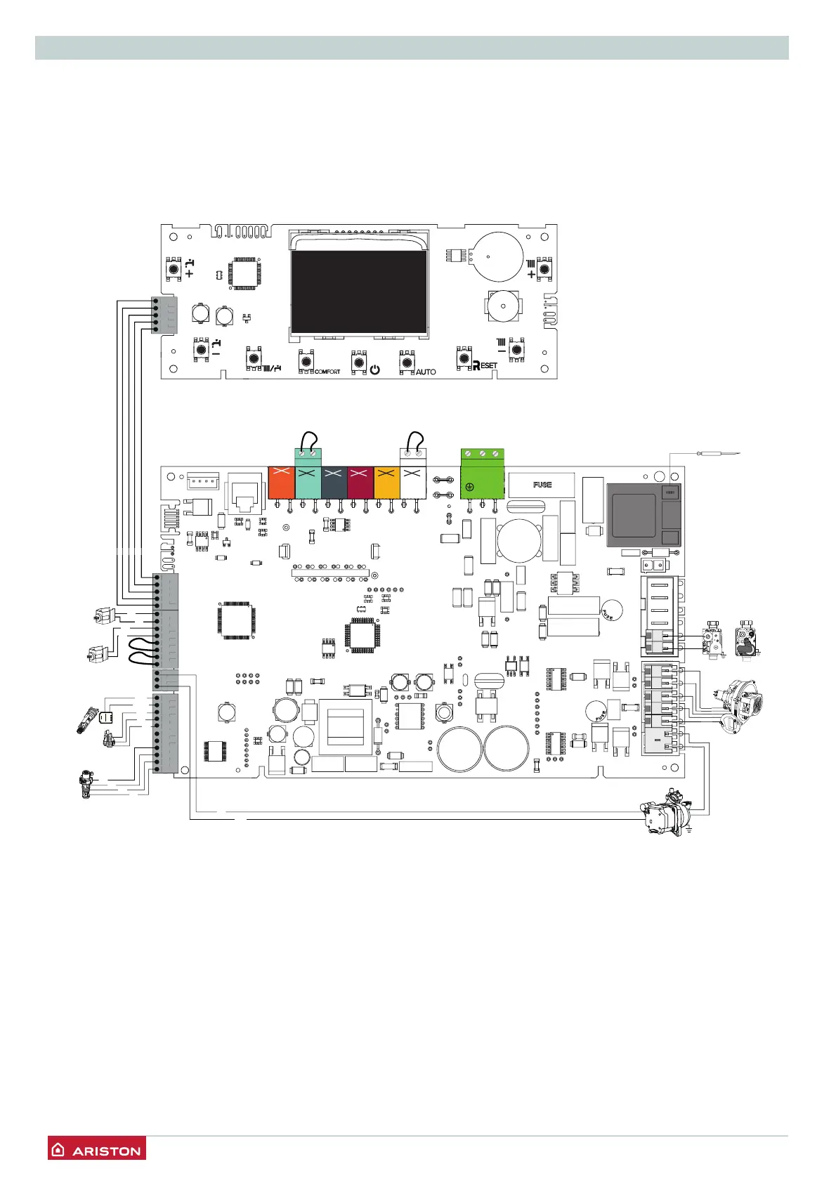
Electrical diagram
For increased safety, ask a qualifi ed technician to perform a
thorough check of the electrical system.
The manufacturer is not responsible for any damage caused by
the lack of a suitable earthing system or by the malfunctioning
of the electricity mains supply.
E-COMBI ONE
NL
NL
BUS
TB
FLOOR
TA2
230 V
SE TNK SOL TA1
230 V
230 V 230 V 230 V 230 V
Bk
Bk
Gry
Bk
Bl
Br
Bk
Bl
Rd
Wh
Br
Bl
Rd
Bl
Bl
Rd
Br
Bk
D.H.W.
flow switch
Switch ON/OFF
Diverter valve
C.H. return
temperature
probe
C.H. flow
temperature
probe
Detection/Ignition
electrode
GAS VALVE
Modulating
fan
Modulating circulation
pump
848
or
8205
1324

Table of Contents