/ 9
PRODUCT DESCRIPTION
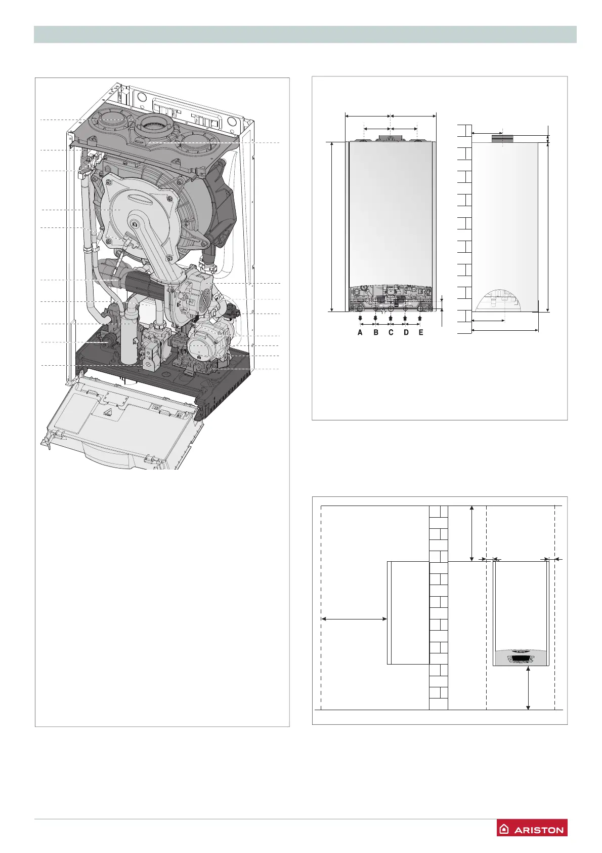
Overall view
1. Flue connector
2. Air relief valve
3. C.H. Flow temperature probe
4. Main heat exchanger
5. Detection Electrode
6. Air/Gas Mixer
7. Secondary heat exchanger
8 Condensate trap
9. C.H. pressure relief valve
10. Gas valve
12. C.H. circuit fi lter
13. Circulation Pump with air release valve
14. D.H.W. Flow switch
15. Diverter valve
16. Switch On-Off
17. C.H. Return temperature probe
18. Modulating Fan
19. Silencer
20. Combustion Analysis Test Point
Overall Dimensions
150
315 (Mod. 24)
385 (Mod. 30/35)
180
25745
745
200
120 120
200
28
65 6567 67
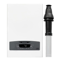
E-COMBI ONE
A. Central Heating Flow
B. Domestic Hot Water Outlet
C. Gas Inlet
D. Domestic Cold Water Inlet
E. Central Heating Return
Minimum clearances
In order to allow easy access to the boiler for maintenance
operations, The boiler must be installed in accordance with the
clearances stated below.
450
053
003
50 50
1
2
5
6
8
9
10
12
13
14
15
16
17
2
18
4
7
3
 Loading...