installation
20
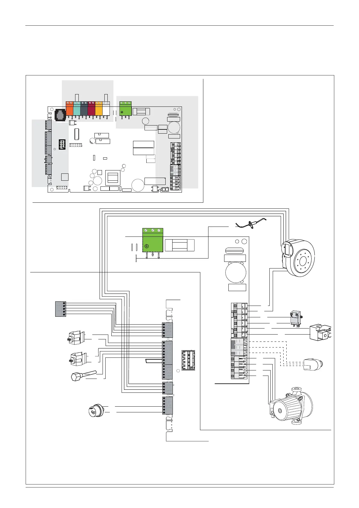
Electrical diagram
For increased safety, ask a quali ed technician to perform a
thorough check of the electrical system.
The manufacturer is not responsible for any damage caused by the
lack of a suitable earthing system or by the malfunctioning of the
electricity mains supply.
N
N
FLAME
L
L
BUS
TB
TA2 SE TNK SOL TA1
CN14
CN13
CN9
1
CN19
CN1
1
1
CN8
1
CN6
1
1
Peripheral unit
LV connections
HV connections
HV connection
N
N
FLAME
L
L
CN19
CN2
CN11
1
1
Gr
Detection electrode
Fan
Rd
Wh
CN11
1
LV connection
Display
C.H. Return
temp. probe
C.H. Flow
temp. probe
Minimum water
pressure switch
Rd
Rd
Bl
Bl
Br
Bk
CN14
CN3
1
1
CN8
1
CN25
1
Ignitor
Diverter valve
CN9
1
Circulation Pump
Bk
Bk
Bk
Bk
Gas valve
Bk
Bk
Br
Bl
Br
Br
Flue
thermostat
GENUS PREMIUM EVOHP 45/65
 Loading...