56 /
INSTALLATION
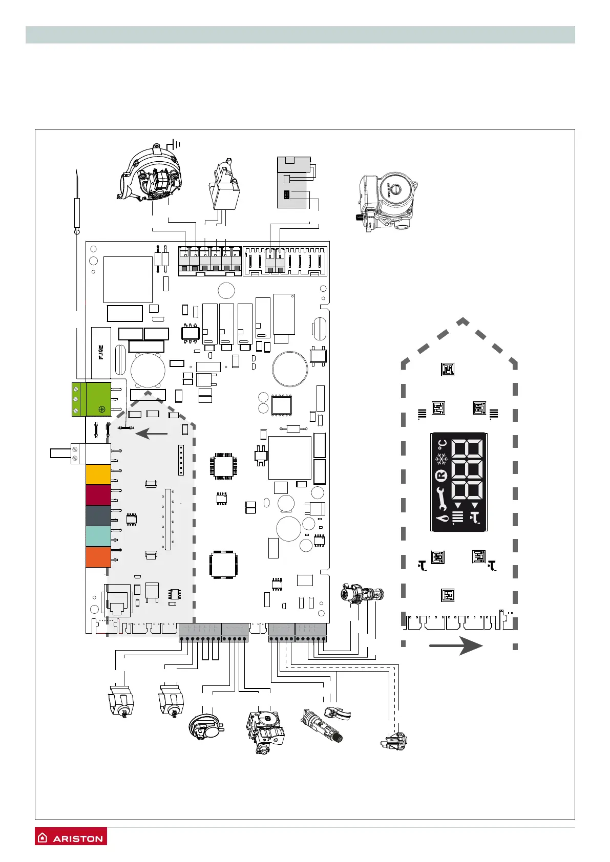
Electrical diagram
For increased safety, ask a qualied technician to perform a
thorough check of the electrical system.
The manufacturer is not responsible for any damage caused by
the lack of a suitable earthing system or by the malfunctioning of
the electricity mains supply.
ON/OFF
+ +
-
RESET
-
CN16
CN14CN10CN5
CN12
CN11
CN8
CN4
CN9
CN2
CN15CN17
11
1
1 1 1
11
1 1
BUS
T B
TA2 SE TNK SOL TA 1
1
N L
N L
C.H. return temperature probe
C.H. flow temperature probe
Air pressure
switch
Gas valve
D.H.W.
Flowmeter
Rd
Rd
Bl
Bl
Detection electrode
Spark generator
Fan
Circulation pump
Br
Br
Wh
Wh
Br
Bk
Bk
Gry
Bk
Wh
Bk
Rd
Rd
Bl
Switch ON/OFF
Diverter valve
Display
1
4
Wh
Br
Bk
Rd
Gry
Br
Bk= Black
Rd = Red
Gr = Green
Bl = Blue
Br = Brown
Wh = White
Gry = Grey
 Loading...