60 / GB
TABLE OF ELECTRICAL CONNECTIONS
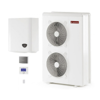
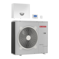
EXTERNAL UNIT
40 S EXT 50 S EXT 70 S EXT 70 S-T EXT 90 S-T EXT
110 S-T
EXT
Nominal running current / phase A 6.4 8 11 3.8 6 7.3
Maximum running current / phase A 9 11 16 5.4 8.4 10
Circuit breaker size A 16-C type 16-C type 20-C type 10-C type 12-C type 12-C type
Nominal Voltage V 230 230 230 400 400 400
Operating voltage limits V 216-243 216-243 216-243 376-424 376-424 376-424
Cos phi > 0,9
Power supply cable
Reference H07RN-F
3G4 3G4 3G4 5G4 5G4 5G4
Max φext 16.2 16.2 16.2 19.9 19.9 19.9
Communication cable
Reference H05RN-F
Type 3x0.75mm
2
INTERNAL UNIT
WH 40 50 S
WH 70 S WH 90
110 S
Electrical supply
V - ph - Hz 230 - 1 -50 230 - 1 -50 400 - 3 -50 230 - 1 -50 400 - 3 -50
Admitted voltages eld V 196 ÷ 253 196 ÷ 253 340 ÷ 440 196 ÷ 253 340 ÷ 440
Rated power input kW 4 4 6
Max current
A 18 18 30 10Axph, 30AxN
Thermal cutout/
di erential circuit breaker
A 20A - type B 20A - type B 32A - type B
Supply cable dimensions H07RN-F 3 x 4 mm
2
Wiring signal EDF, AFR, PV mm
2
H07RN-F 2 x 0,75 mm
2
Supply cable
mm
2
H07RN-F 3 x 4 mm
2
MOD BUS
cable
mm
2
H07RN-F 3 x 0,75 mm
2
Power supplies of the indoor and the outdoor units are to be respectively connected to a circuit breaker (RCCB) with minimum threshold of 30 mA.
ATTENTION
The electrical connections shall be made after completing all hydraulic connections.
The internal and external units must be powered separately according to what is indicated on the tables. Between the internal
and external units should also be made a MOD BUS connection. This connection may be made through the use of a cable of
reduced section (recommended section 0,75 mm
2
). Do not let this cable walk along a power connection.
Electrical circuit
• Check that the voltage and frequency of power supply from the network coincide with the data shown in the data plate of the
appliance (see table)
• In order to ensure greater security, the main electrical system should be checked by a quali ed technician before proceeding
with the installation (see note).
• The manufacturer is not liable for any damage caused by installation with improper grounding or abnormalities in the electrical
system.
• Check that the installation is adequate to support the power consumption of the installed units, indicated on the data plate of
the product.
• The electrical connections must be carried out with the aid of a xed supply connection (do not use mobile sockets) and equip-
ped with a bipolar switch, having a distance between the contacts of at least 3 mm.
• It is essential to connect the appliance to a correctly grounded electrical circuit, as to ensure the safety of the installation.
It is also forbidden to use for the grounding of the system and the hydraulic connection of the heating tubes.
• The manufacturer is not liable for any damage caused by installation with improper grounding or implant level anomalies elec-
tric.
• Connect the power cord to a 230V-50Hz or (400V-50Hz), verifying the polarizations of the L-N (or L1, L2, L3, N) connection and
the connection to the earth. The section of the used cables must comply with the power of the installation (see plate characte-
ristic).
• For the electrical connection of the installation, you shall not use power strips, extension cords and adapters. It is also prohibited
to use the hydraulic pipes and heating system pipes to ground the installation.
The system is not protected against lightning. If you need to change the fuses, use fast fuses.
Warning: Before obtaining access to terminals, all supply circuits must be disconnected.
ELECTRICAL WIRING
 Loading...