61 / GB
WARNING:
Make ground connection prior to any other electrical connections.
The internal and external units must be powered separately.
To prevent any risk, the power supply cable of the outdoor and indoor unit must only be replaced by the technicians of the
after-sales service.
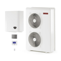
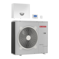
External Unit electrical connection
• When removing the front panel, the electric parts appear at the front side.
• The power supply cables can be inserted into the precut holes (A) (Take o the knockout part)
• Be sure to x the power cable (B) and indoor/outdoor communication cable (C) with all the clips provided into the units and if necessary
add bundling bands sold on the market in order to be sure that they will not be in contact with the compressor and the hot pipes.
• To ensure good tensile strength, the electric cables must be fastened using the cable-holder on the plate (D).
• Connect the communication cable to the terminals as identi ed by their respective numbers on the terminal block of indoor and
outdoor unit.
According to the installation instructions, all devices for disconnection from the power supply mains must have a contact opening (4 mm)
to allow total disconnection according to the conditions provided for the overvoltage class III.
Warning: Before obtaining access to terminals, all supply circuits must be disconnected.
L NNL
MODBUSMODBUS
GND
AB LN
GND
A B L1 L2 L3 N
Low voltage Low voltage
External unit terminal block 1Ph External unit terminal block 3Ph
High voltage High voltage
A
B
C
D
 Loading...