Do you have a question about the Ariston TVM63X NA and is the answer not in the manual?
Important safety precautions and general advice for servicing the appliance.
Explanation of serial number and industrial code formats for model identification.
Describes the airflow and drying process within the tumble dryer.
Explains the automatic drying system, its requirements, and limitations.
Lists and explains available drying programmes like Timed Drying and Easy Iron.
Explains the function and types of timers used in the drying process.
Explains the operation of the door lock and interlock system.
Details the heater element, its construction, and interchangeability.
Explains the function and replacement of the safety cut-out thermostat.
Describes the cycling thermostat that limits drum temperature.
Details the motor, its speed, protection, and associated capacitor.
Provides a detailed wiring diagram for the appliance.
Emphasizes safety when disassembling the appliance, like unplugging.
Instructions for removing the heater assembly and its thermostats.
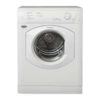
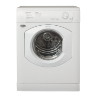
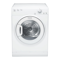
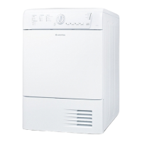
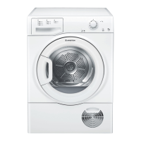
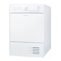
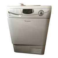
This document serves as a service manual for Ariston Electromechanical Vented Tumble Dryers, specifically covering the TVM63X NA model. It provides essential information for qualified technicians regarding the appliance's function, operation, and maintenance.
The tumble dryer operates by drawing cold air into the cabinet through louvres in the base. This air then passes through a large hole in the inner back panel, driven by a fan, and is directed through the element housing. After being heated by the element windings, the warm air enters the drum through holes in the drum back plate. Inside the drum, the warm air circulates through the load, extracting moisture from the damp fabric. A webbing seal on the inner back panel prevents warm air from escaping into the cabinet interior.
As the drum revolves, the clothes are tumbled through this warm air stream. The now moist and cooled air then passes through a filter located in the air duct on the back of the front panel, where lint and fluff are removed. Finally, the air travels through the front-to-rear air duct and exits the dryer at the rear outlet. A vent hose can be attached to this outlet to direct exhaust air away from the dryer.
The heating system incorporates safety features. A cut-out on the element housing interrupts the Live electricity supply to the element if the air temperature becomes too high, typically due to restricted airflow (e.g., a blocked filter). This cut-out automatically resets once the air temperature drops to an acceptable level and will cycle if the fault persists. A secondary 'one-shot' cut-out, positioned alongside the 'auto reset' cut-out, acts as a safety device to break the element Neutral connection if the air temperature reaches an unsafe level due to a failure of the 'auto reset' cut-out.
Two thermostats are located in the front air duct. Depending on the selected program, only one is active at a time. These thermostats sense the exhaust temperature rise as the load dries, and when the clothes are dry, they energize the timer motor on the main timer, allowing it to advance to the cool run phase.
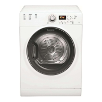
The dryer offers various drying programs and heat settings, controlled via a console panel. The console includes a timer knob for selecting timed and sensed drying periods, and a push switch for heat selection.
The Timer 1 (Programme Timer), mounted on the console, controls the motor and heating during drying programs. It features a timed cycle of up to 170 minutes of heated drying, followed by a 7.5-minute cool run. An 'Eco' program is available, which provides heated drying until a thermostat operates (indicating the load is dry), after which the timer advances to a 7.5-minute cool run. The cam of this timer pauses on the heated part of the cycle by cutting the circuit to its motor. The dryer motor continues to reverse, controlled by Timer 2. When the load is dry, a front duct thermostat powers Timer 1's motor, allowing it to advance to cool run. An optional crease removal program is also provided, consisting of 7.5 minutes of heat and motor operation, followed by a 2.5-minute cool tumble.
The Timer 2 (Reversing Timer), mounted on the base panel, controls the motor's reversal during drying programs, changing direction approximately every 2.5 minutes.
The Heat Switch is a normally open push-push switch on the facia moulding, allowing users to select high or low heat settings. Operating this switch selects either all or half of the heater unit. The 'IN' position corresponds to full heat, and the 'OUT' position to low heat. For automatic drying programs to function correctly, high heat must be selected; otherwise, the dryer will advance to cool run without drying the load.
The START button initiates the selected program. The HEAT button selects the drying temperature. The Drying Guide on the console provides a user-friendly table of fabric types, load capacities, and available programs. The TIMER / PROGRAMMES knob sets the drying time or program. It should always be rotated clockwise, never anti-clockwise, until the indicator points to the desired time or program.
Automatic Drying requires the high heat setting to be enabled and is optimized for cotton loads between 3 Kg and 6 Kg. Using automatic drying for smaller or delicate loads may yield erratic results. The automatic drying sequence begins with 20 minutes of full heat, controlled by the timer, to pre-heat the clothes and drum. The timer then advances to its next cam position, disconnecting the timer motor while the dryer continues to tumble and heat. When the clothes are dry, the exhaust thermostat opens, providing a Live supply to the timer motor, which then advances the timer to the next cam position. This is followed by 5 minutes of tumbling with only the lower element, and finally 7.5 minutes of tumbling with no heat.
The Easy Iron program is a short 10-minute cycle (8 minutes of heat followed by a 2-minute Air Fluff period) designed to soften clothing fibers that have been left in the same position for an extended period. It relaxes the fibers, making them easier to iron and fold. It is not a drying program and should not be used for wet articles of clothing. For best results with Easy Iron, do not exceed maximum load capacities (e.g., 5.5 lb / 2.5 kg for Regular Cotton) and unload the dryer immediately after the program ends.
The manual provides detailed dismantling instructions for various components, emphasizing safety precautions such as unplugging the machine and being aware of sharp edges.
Top Cover Removal: Involves removing two screws from the back panel, sliding the cover back, and lifting it clear.
Console Panel Removal: Requires removing the top cover, two screws securing the timer mounting plate, disconnecting wiring to option switches, unclipping the start relay, removing two screws securing the console to side panels, removing a screw securing the front panel to the side panel, lifting locking tabs, and finally depressing locking tabs to remove timer knobs.
Programme Timer Removal: Similar to console removal, focusing on the timer's mounting plate and wiring.
Door Lock Removal: Involves removing the top cover and right-hand side panel, disconnecting wiring, and using a special tool (Part No. C00222677) to depress locating pips and slide the switch from the front panel.
Option Switches Removal: Requires gripping and pulling off switch caps, noting wiring connections, and depressing locking tabs.
Side Panels Removal: Involves removing the top cover, pulling the plinth forward, removing screws behind the plinth, securing the side panel to the front and rear panels, and pulling the panel backward to disengage from base lugs.
Front Panel & Air Duct Removal: Requires removing the top cover, console, plinth, screws securing the front panel to the base, and disconnecting wiring to air duct thermostats and the door switch.
Energy Save Thermostat Removal: Involves removing the right-hand side panel or front panel, disconnecting wiring, and removing two screws.
Door Seal Removal: Requires removing the front panel and air duct, separating the air duct from the front panel, and then removing the seal.
Door Removal: Involves opening the door, removing four screws securing the door assembly to the front panel, removing a screw for the door latch, a screw behind the latch for the handle, and six screws securing the two halves of the door assembly to access internal components.
Door Hinges Removal: Requires the door to be removed and split, then turning hinges inwards and sliding them upwards from the rear trim moulding.
Front Bearings Removal: Involves removing the front panel, springing the fixing lug from the mounting bracket, and sliding the pad.
Drive Belt Removal: Requires removing the right-hand side panel and using a Special Tool (Part No. C00142716) to release the belt from the motor shaft. The belt should be slid off the drum and passed between the drum front and front panel.
Drive Belt Fitting: Involves sliding the new belt onto the drum, replacing the front panel, and using the Special Tool to ease the belt onto the motor shaft by rotating the tool.
Capacitor Removal: Requires removing the right-hand side panel, noting wiring connections, disconnecting leads, and removing the securing nut.
Drum Assembly Removal: Involves removing the top cover, console, front panel, right-hand panel, rear bearing cover, rear bearing fixing screw, drive pin, and shaft collar. A new drive pin must be fitted during reassembly.
Heating Assembly & Thermostats Removal: Requires removing the right-hand side panel, disconnecting wiring to the heater assembly, removing the bearing cover, screws securing the heater assembly to the rear panel, and screws retaining the element and thermostats. If either the cycling or one-shot thermostat fails, both must be replaced. Care must be taken to ensure heater wiring is not trapped during reassembly.
Rear Bearing Removal: Involves removing the plastic, fan-shaped bearing cover, drive pin, bearing fixing screw, and sliding the bearing off the drum shaft. The correct bearing fixing screw must be used to maintain drum earthing.
Rear Seal Removal: Requires removing the drum, cleaning remnants of the old seal and adhesive, and fitting a new seal using adhesive Part No. C00981027.
Motor Removal: Involves removing the right-hand side panel, heater cover, and two fans from the motor hub (three hex head screws). The inner and outer fans are different and must be reassembled in the correct order. Wiring connections must be noted, and the motor disconnected at the in-line connector and capacitor. The drive belt must be disengaged from the motor shaft. Finally, three hex head screws securing the motor to its cradle and two screws securing the cradle to the base panel (if necessary) are removed. Care must be taken to ensure heater wiring is not trapped when refitting the heater cover.
| Appliance placement | Freestanding |
|---|---|
| Rated capacity | 6 kg |
| Color | White |
| Loading type | Front load |
| Drying Programs | Cotton, Synthetics, Delicates |
| Width | 60 cm |
| Height | 85 cm |