4 1X-F Series Operation Manual
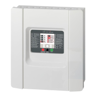
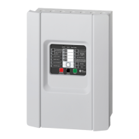
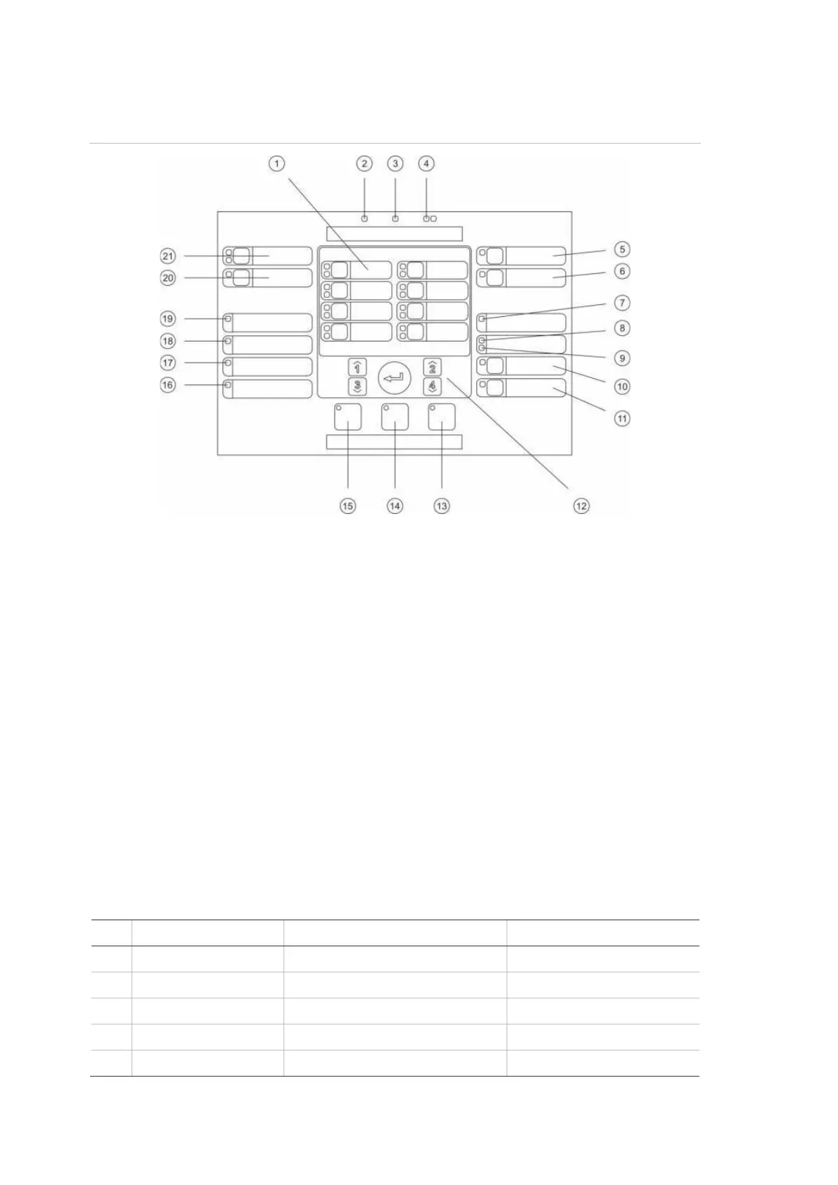
User interface for eight-zone control panels
Figure 2: User interface for eight-zone control panels
. Zone buttons and LEDs (Z1, Z2, etc.)
. Supply LED
. General Fault LED
. General Fire Alarm LEDs
. Sounder Fault/Disable/Test button and LED
. Sounder Delay button and LED [2]
. Networking Fault LED
. Service Detector LED [2]
. Expansion I/O Fault/Disabled LED
. General Disable button and LED
11. General Test button and LED
12. Configuration controls
13. Reset button and LED
14. Panel Silence button and LED
15. Sounder Start/Stop button and LED [2]
16. System Fault LED
17. Out of Service LED
18. Earth Fault LED
19. Supply Fault LED
20. Fire Routing Delay button and LED [1][2]
21. Fire Routing ON/ACK and
Fault/Disable/Test button and LEDs [1][2]
Two-zone control panels do not include fire routing or warning sounders for NEN 2535.
[2] Regional variants include changes to interface buttons and LEDs as shown in Table 4 below
Table 4: Regional variants of interface buttons and LEDs
EN 54 NEN 2535 NBN S 21-100
Sounder Delay Fire Protection Fault/Disable/Test Evacuation Sounder Delay
Service Detector Fault Warning Fault/Disabled Service Detector
Sounder Start/Stop Sounder Start/Stop Evacuation Start/Stop
Fire Routing Delay Fire Routing Delay Warning Sounder Delay
Fire Routing ON/ACK Fire Routing ON/ACK Warning Sounders Start/Stop
 Loading...