EN: Installation Manual
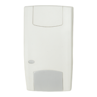
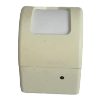
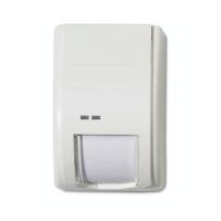
2000 series sounders and beacons are designed for use
in Aritech analogue addressable fire systems running
the 2000 Series protocol. The sounders can be put into
different operating modes.
CAUTION: This product must be installed by qualified
personnel adhering to the TS54-14 specification and any
other applicable local authority regulations.
If required, the mechanism for locking the sounder to
the base can be activated by removing the thin section
of plastic shown in Fig. 1a with side cutters or a similar
tool. To open a locked head, remove the small rubber
bung from the hole on the side of the sounder, insert
a tool into the hole and depress the clip whilst twisting
the head. The O-ring and bung must be re-fitted to
maintain the weatherproofing.
An alternative locking method is shown in Fig. 1b.
Drive the hexagonal locking screw forward by turning a
1.5mm hexagonal key clockwise until the head is locked.
Wiring
Line Terminal Marking
Line (positive) (3) L +
Line (negative) (2) L -
A separate earth terminal is provided on the deep base
for connecting the screen or functional earth. On the
shallow base, terminal 5 can be used for this purpose.
Addressing
Each device requires a numeric address between 1 and
128 for identification purposes. This is set using switches
1-8 on the Address Selector switch (see Figure 2).
When this device is used in conjunction with the
FP1200/2000 range of fire panels, it must have an
address of 80 or higher when it is used as a sounder
and beacon. When an address lower that 80 is assigned
to the device, it will function as a sounder only, without
the beacon flashing.
Tone selection/Volume control/Flash rate
a. The device tone is set using switches 1-5 on the Tone
Selector DIP switch (see Figure 2a). See tone table for a
complete list of tone/DIP switch settings.
b. Switch 6 on the Tone Selector DIP switch is used to
select the sound volume (See Figure 2b). The default
setting (switch OFF) is high volume. Changing the
switch to ON reduces the sound output by 8dB.
c. Switch 7 Flash rate: 0.5Hz =OFF/1Hz =ON (See Figure
2c).
Maintenance and testing
Basic maintenance is reduced to an annual inspection.
Do not modify internal wiring or circuitry. Test all devices
after installation.
Products marked with this symbol cannot be
disposed of as unsorted municipal waste in the
European Union. For proper recycling, return this
product to your local supplier upon the purchase
of equivalent new equipment, or dispose of it at
designated collection points. For more information see: www.
recyclethis.info.
Supply Voltage Range 17- 32Vdc
Switch on Surge @ 24Vdc <1.2mA
Current (mA):
Panel Loop
Alarm Beacon @ 24Vdc 0.5Hz 20
Alarm Beacon @ 24Vdc 1Hz 40
Alarm Sounder/Beacon @ 24Vdc 0.5Hz 25.1
Alarm Sounder/Beacon @ 24Vdc 1Hz 45.1
Standby 0.31
Sounder:
Number of Tones 32
Peak Sound Level 97dBA @ 1m*
Frequency Range 400 - 2850 Hz*
Beacon:
Flash Rate 0.5Hz/1Hz
White Flash Coverage (ceiling) C-3-15 (530m
3
)
White Flash Coverage (wall) W-3.5-11.5 (395.84m
3
)
Red Flash Coverage (ceiling) C-3-9 (190m
3
)
Red Flash Coverage (wall) W-3-7.49 (168m
3
)
Environmental:
Humidity 5% to 95%
Operating Temperature -10°C to +55°C
Storage Temperature -10°C to +55°C
Casing High Impact
Polycarbonate
Weight (shallow base) 298 g
Weight (deep base) 345 g
Device Type Code 0E (H)
Cable Size min.0.28 mm2
max.2.5 mm2
IP Rating IP21/IP65 (deep base)
Synchronisation Automatic
*EN54-3 certied on tones 1,2,3,6,7 and 13.
Technical Specification
Troubleshooting
Before investigating individual units for faults, check the
system wiring is fault free. Earth faults on data loops may
cause communication errors.
Problem Possible Cause
No response or
missing
Incorrect address setting or incorrect
loop wiring (polarity reversed)
Device fails to
operate
Control panel has incorrect cause
and eect programming
www.acornfiresecurity.com
www.acornfiresecurity.com