14 1791 999 7
All programmed features can be changed. The structure and position of the programming options
are illustrated in the Programming Map on the next page. Features and options are grouped together
and allocated to 6 main menu blocks:
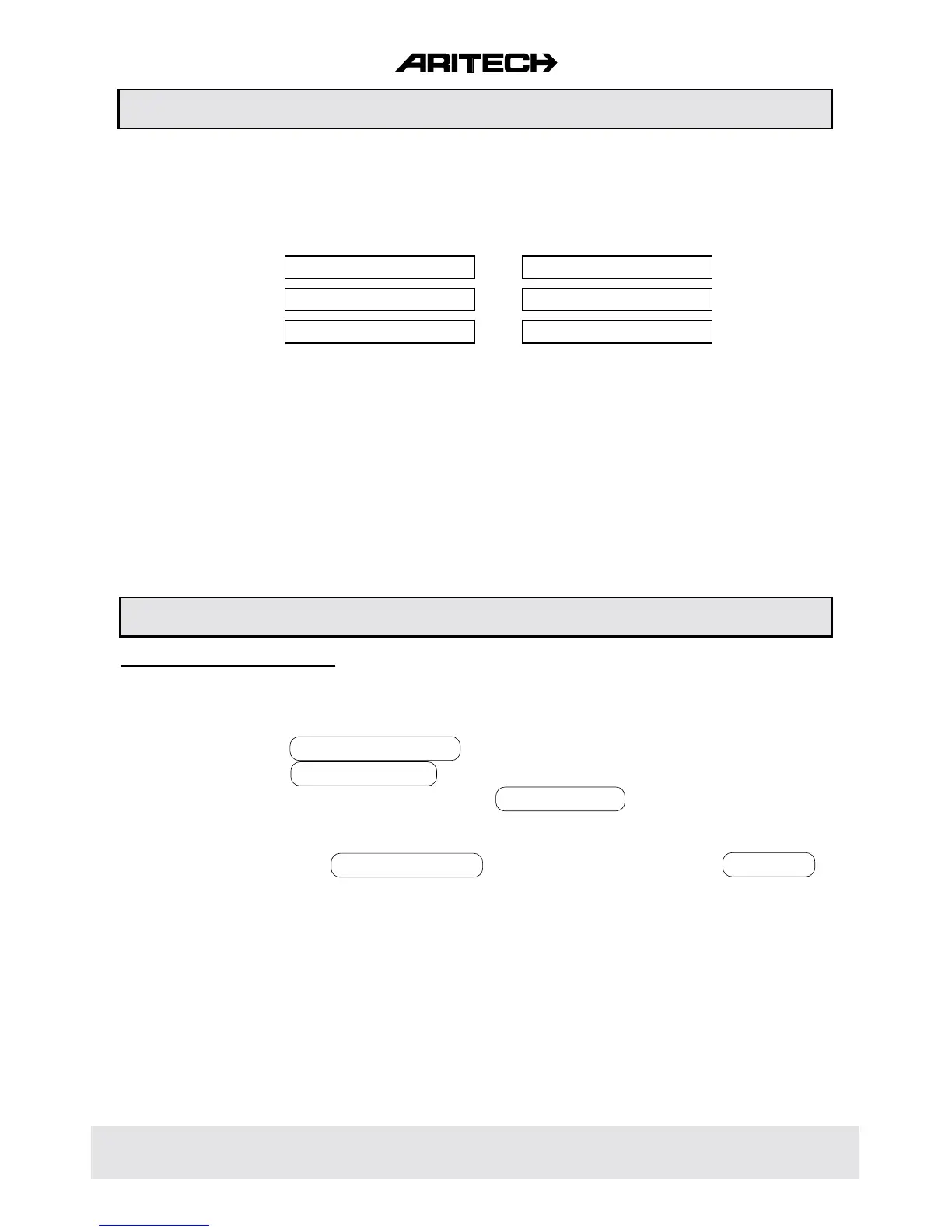
1 MAINTENANCE 4 ZONES
2 TIMERS 5 OUTPUTS/REMOTES
3 USERS 6 MISCELLANEOUS
Once in Engineer Mode, the blocks can be accessed by 'stepping' through the menu blocks and
accepting the option shown in the display. The keys used for programme selections are defined as
follows:
[ê] stepping forward to next block or programming option
[é] returning to previous block or programming option
[ü] enter programming block - enter programming option - confirm changes - accept option
[X] quit programming block - quit programming option - reject changes
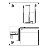
After have installed the additional keypads - mind the correct dipswitch ID setting - go to the Engineer
Programming Mode and proceed as follows:
1. Use the [ê] key till OUTPUTS/REMOTES is displayed then enter [ü] .
2. Use the [ê] key till INSTALL REMOTE is displayed then enter [ü] .
3. The display shows the keypads connected, eg. REMOTE k k ✱ ✱ . Confirm [ü] these changes
when they are correct. If not correct, verify the wiring to the keypad and dipswitch ID settings.
The keypad must be powerless when changing dipswitch settings.
4. The display now shows INSTALL REMOTE . Quit programming blocks [X] till GOODBYE is
displayed. Now accept [ü] to leave the Engineer Programming Mode.
HOW TO PROGRAMME
Adding Additional Keypads
PROGRAMMING EXAMPLE