- 3 -
English
MOUNTING INSTRUCTIONS (fig. 1a).
• Lift off cover plate
as shown.
• Open detector
and remove electronics module
, taking care not to touch
pyroelectric sensor
.
• Break out one or both cable entry hole(s)
as required.
• Select mounting holes for corner
or flat wall
mounting.
• Use the base as a template for marking screw hole locations on the wall.
• Fasten the base to the wall.
• Strip cable for 5 cm and pull it through the cable entry hole(s)
and strain
relief
(fig. 1b).
• Replace the electronics module
and wire the detector as shown (fig. 2).
• Select options with switch as required (fig. 2), replace cover
, insert
screw
and replace cover plate
.
• The detector should be mounted at a height of 1.8 to 3.0 m. for EV435AM/
EV436AM (fig. 1c) and 1.8 to 5.0 m. for EV455AM/EV456AM (fig. 1e).
SITING THE DETECTOR (fig. 1c).
Install the detector so that the expected movement of an intruder will be across
the fields of view. This is the direction best detected by PIR detectors.
As for all PIR's the following false alarm sources should be avoided:
- Direct sunlight onto the detector.
- Heat sources in a field of view (heaters, radiators, etc.).
- Strong air draughts onto the detector (fans, air conditioning etc.).
- Large animals in a field of view (dogs, cats).
REMOTE ENABLE/DISABLE OF WALK TEST LED (fig. 2).
To walk test the detector, the "CV" to terminal 9 (latch) must be disconnected.
Connect "CV" to terminal 10. The detector’s LED will now light and go out again
as the alarm relay opens and closes, making possible walk testing.
Note 1: Enabling the walk test will not clear alarm memory. After disarming the
system after an alarm, you may switch to walk test. When you switch back out
of walk test, the indication of memorized alarms will re-appear. Only when "CV"
is re-applied to terminal 9 (ie. system is re-armed) will LEDs and memory be
cleared.
Note 2: To enable the walk test LED without a remote "CV" input, connect a link
between terminal 2 and 10.
Note 3: Aritech recommend that the detector is regularly walk tested and checked
back at the control panel.
Switch 1: LED indication:
"ON " enables both LED's on the detector at all time.
"OFF " puts both LED's under the control of the Walk test input when the
system is disarmed.
Switch 2: Range:
"ON " selects max. stated range. i.e 16 m for EV435AM/EV436AM.
25 m for EV455AM/EV455AM.
"OFF " selects min. stated range. i.e 10 m for EV435AM/EV436AM.
15 m for EV455AM/EV455AM.
Switch 3: Processing: (EV435AM/EV436AM).
"ON " enables Bi-curtain processing, designed for harsh environment.
"OFF " provides the Aritech 4D processing.
Note 4: Bi-curtain is used to reduce the possibility of false alarms. It looks for
signal verification and requires the intruder to be seen in two curtains for an
alarm.
Switch 4: How to signal "Trouble output":
"ON " signals the AM-trouble signal on both the ETO and alarm relay.
signals the technical fault to ETO only.
"OFF " signals the AM-trouble and technical fault on the ETO.
Switch 5: AM Sensitivity:
"ON " selects a higher level of AM sensitivity.
"OFF " selects the standard AM sensitivity.
Switch 6: Resetting the "Trouble output":
"ON " resets the Trouble output after PIR-alarm.
"OFF " resets the Trouble output only when authorized.
Switch 7: When to indicate the "Trouble output":
"ON " will signal a Trouble only, when the system is disarmed.
"OFF " will signal the Trouble output immediately.
Switch 8: Control polarity:
"ON " provides the standard Aritech logic with active high logic to enable
Walk test and Latch inputs.
"OFF " provides active low logic to enable Walk test and Latch inputs.
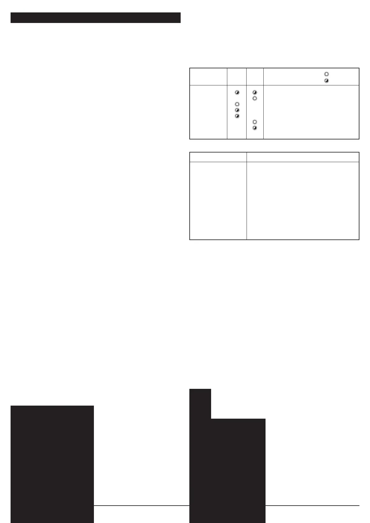
THE INDICATION OF THE LED'S is controlled with switch 1.
3 If switch 1 is ON then the following indications are shown at all times.
3 If switch 1 is OFF then the following indications are only shown when the
system is Disarmed and the Walk test line is enabled.
Detector Yellow Red Comment = light
status LED LED = flash
Power on Alternately flashing for 20 sec.
Alarm ----- For alarm period - nominally 3 sec.
AM ---- Until AM reset.
PIR Trouble
---- Flashing slowly until reset.
AM Trouble
---- Flashing quickly until reset.
Low Battery --- Always on until correct voltage restored.
Latch alarm --- Flashing until reset.
(not displayed during Walk test).
RESET CONDITION
Detector status Condition for reset
PIR Alarm 3 sec. time-out.
PIR Latched alarm Next change from "disarm" to "arm".
AM (auto - reset) Next successful PIR alarm after a 40 sec.
inhibit period.
AM (authorized reset) Next successful PIR alarm in "disarm" and
"walk test" mode.
PIR Trouble Next successful PIR alarm.
Next successful automatic test (every 10 minutes
during "disarm").
AM Trouble Next successful AM detection.
Next successful automatic test (every 10 minutes
during "disarm").
ALARM MEMORY (fig. 3).
Note: First set the Control Voltage ("CV") by switch 8 (fig. 2).
(For example: switch 8 = "Off", then "CV" = 0 Volt = "Low").
Connect "CV" to terminal 9 when the system is armed. When system is
disarmed, disconnect the "CV". If an alarm has occured during the armed period,
the detector or detectors which gave the alarm are indicated by a flashing LED.
Re-applying the "CV" (re-arming the system) will reset LED indication and
memory.
SELECTING THE COVERAGE PATTERN (EV435AM/EV436AM fig. 4-9).
Mask the appropriate mirror curtains with the adhesive labels provided and
reassemble the sensor module.
For example:
See fig. 4 for mirror curtain coverage pattern corresponding to curtain 2A & B,
7A and 9B masked.
Removing label(s) can damage the mirrorsurface!
The coverage pattern can be changed to fit specific requirements using the
mirror masks as shown (fig. 5-9). Mask off unused curtains which might
otherwise be looking at walls or windows very close to the detector.
Remark: The range of the detector can, under optimal conditions, be up to
100% higher as stated.
WINDOW MASK (EV435AM/EV436AM-fig. 10 & EV455AM/EV456AM-fig.12).
In the presence of objects close to (within 1.5 m) and directly under the detector,
fit the mask to the inside of the window.
This disables the part of the curtains looking at the object, whose closeness
might otherwise destabilize the detector. In particular, use the mask to avoid
objects of changing temperature (e.g. drinks machines, caged birds, etc.) and
reflective surfaces.
- 3 -
 Loading...