2 / 24 P/N 10-5106-501-34NC-01 • 16MAR18
EN: Installation Sheet
Description
This document includes installation information for the
IO2034NC I/O Module. The module provides four inputs and
four outputs and is designed for use with FP1200C-2000C and
2X Series addressable fire systems.
Figures
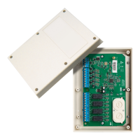
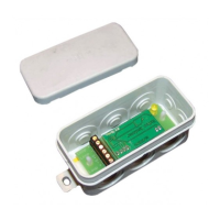
1: Module assembly
2: Module layout
(1) Fault LED for open or short
circuit on supervised inputs
Rotary dials for module
addressing
COM2 supply voltage input
(4) COM1 supply voltage input
(negative)
5) Inputs A to D
6) Outputs A to D (NC, COM,
NO)
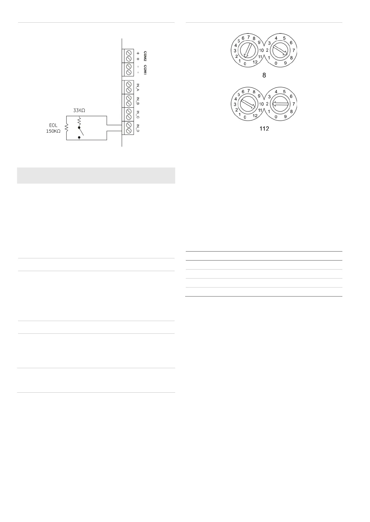
3: Fully supervised input wiring
4: Example address settings
Installation
Caution: For general guidelines on system planning, design,
installation, commissioning, use, and maintenance, refer to the
EN 54-14 standard and local regulations.
Assembly
Install the module into the protective housing as shown in
Figure 1. Connecting cables should be fed through the cable
entry hole at the rear of the protective housing before the
module is fixed into place.
Wiring
Connect the I/O module to the loop via the COM2 (positive)
and COM1 (negative) inputs.
Inputs A to D each require an end-of-line resistor (150KΩ, 5%,
1/4W), including when not used. Inputs are supervised for
open circuit (ON/OFF) or short circuit (ON/OFF) status. For a
fully supervised input (open and short circuit) an additional
resistor (33KΩ, 5%, 1/4W) must be installed as shown in
Figure 3.
Table 1: Impedance and device state
Device state
– 630KΩ Open (open circuit)
– 68KΩ Passive (contact open)
– 15KΩ Active (contact closed)
– short circuit Short (short circuit)
* 150KΩ EOL included
Addressing
Each module must be assigned an address from 1 to 128. Use
the rotary dial marked 0 to 12 to set the tens and hundreds part
of the address, and the rotary dial marked 0 to 9 for the
remaining digits. See Figure 4 for example address settings.
Note: To overcome the mechanical effects of shipping and
storage, we recommend that you first rotate each dial counter-
clockwise (to the 0 position) and then clockwise (to the dial’s
maximum position) before setting the required address.
To change the address of a module that is operational:
1. Disconnect the module from the loop.
Wait at least 20 seconds for the module to completely
power down.
2. Change the address on the module using the rotary dials.
3. Connect the module to the loop.
4. Configure the device at its new address, and then remove
the old device address at the panel.
www.acornfiresecurity.com
www.acornfiresecurity.com