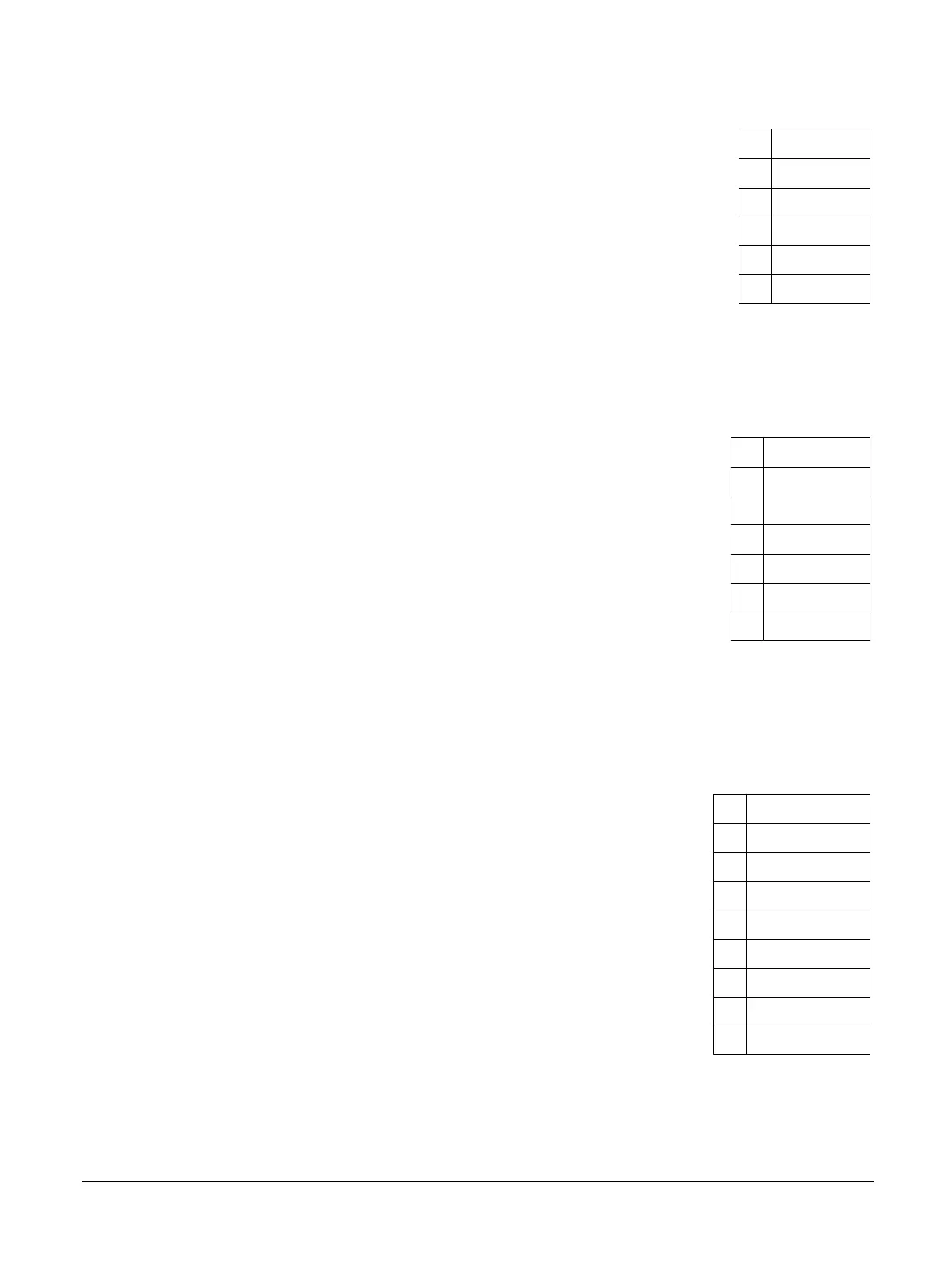
Table A-7 Connectors J30 (Shield 0) and J36 (Shield 1) signal list (continued)
Pin Signal
4 SH0/SH1_IO3
5 SH0/SH1_IO4
6 SH0/SH1_IO5
7 SH0/SH1_IO6
8 SH0/SH1_IO7
Analog I/O connectors: Connectors J29 and J39
Connector J29 provides six analog I/O for Shield 0 and connector J36 provides six analog I/O for
Shield 1. The following table shows the pin mapping for connectors J29 and J39.
Table A-8 Connectors J29 (Shield 0) and J39 (Shield 1) signal list
Pin Signal
1 SHO/SH1_AD0
2 SH0/SH1_AD1
3 SH0/SH1_AD2
4 SH0/SH1_AD3
5 SH0/SH1_AD4
6 SH0/SH1_AD5
Power and voltage references: Connectors J26 and J35
Connector J26 provides power and voltage references for Shield 0 digital I/O. Connector J35 provides
power and voltage references for Shield 1 digital I/O. The following table shows the pin mapping for
Shield connectors J26 and J35.
Table A-9 Connectors J26 (Shield 0) and J35 (Shield 1) signal list
Pin Signal
1 N/C
2 SHO/SH1_IOREF
3 SHO/SH1_nRST
4 3V3
5 5V
6 GND
7 GND
8 SHO/SH1_VIN
Supplementary connectors J27 and J37
The supplementary connectors, J27 and J37, provide subsets of the signals on the main Shield
connectors. Connector J27 provides a subset of the Shield 0 signals and connector J37 provides a subset
of the Shield 1 signals. The following table shows the pin mapping for connectors J27 and J37.
A Signal descriptions
A.2 Arduino Shield connectors
100765_0000_04_en Copyright © 2017–2020 Arm Limited or its affiliates. All rights
reserved.
Appx-A-78
Non-Confidential