# 44876D006 Page 7
ledoM edoM
tatsomrehT
spaTdraoBlortnoC
LOOC TAEH
MUH ME 1W O 1Y/2Y G
A B C D A B C D
MFC MFC MFC MFC MFC MFC MFC MFC
ABS21VFE
rewolB.tnoC
X
006005004053
gnilooC**
XX
00210001008006
gnitaeH
X
00210001008006
***taeH.xuA
XX
************0021*0011*0011*0011
***taeH.remE
XX
************0021*0011*0011*0011
ABM61VFE
rewolB.tnoC
X
009 007 006 005
gnilooC **
X X
0061 0041 0021 0001
gnitaeH
X
0061 0041 0021 0001
***taeH.xuA
X X
*** *** *** *** 0061 0041 *0021 *0001
***taeH.remE
X X
*** *** *** *** 0061 0041 *0021 *0001
ABL02VFE
rewolB.tnoC
X
009008007006
gnilooC**
XX
0081006100410021
gnitaeH
X
0081006100410021
***taeH.xuA
XX
************008100610041*0021
***taeH.remE
XX
************008100610041*0021
NOTES:
* This CFM is not approved for use with highest kW heater size.
** Humidistat will reduce cooling air flow by 10% in high humidity.
*** Airflow is greater of COOL and HEAT when both electric heat and heat pump are operating.
ADJUST tap (+) will increase airflow by 10%, while tap (–) will decrease airflow by 12%.
ADJUST tap TEST will cause the motor to run at 70% of full airflow. Use this for troubleshooting only.
At the start of a call for cooling there is a short run at 82% of airflow for 7.5 minutes.
At the end of a call for cooling there is a blower delay of 1 minute.
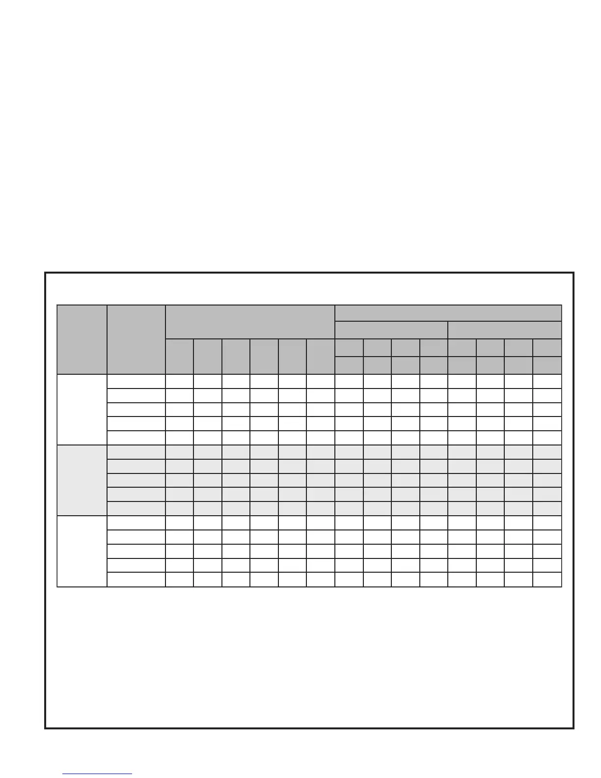
Table 3
Variable Speed Motor Application Table
straight air conditioning system, connect the “O” wire
to the 24 volt “R” wire.
The motor control board that provides airflow selection also
features LED indicators that display operating mode, humidity
control, and airflow CFM. In addition, thermostat signals for
emergency heat (EM), aux. heat (W1), reversing valve (O),
compressor stage 1 (Y1), compressor stage 2 (Y2), and
blower (G) are all indicated by lit LED’s on this board. If a
humidistat is used, the dehumidify LED will light when the
humidistat opens and the motor runs at reduced airflow. The
control board also has a CFM LED that displays the operating
CFM. This red LED flashes once for each 100 CFM. For
example, if the operating CFM is 1200, the CFM LED will flash
12 times, then pause before repeating the 12-flash pattern.
Special note for units equipped with a humidistat: If using
a humidistat, the dehumidify resistor located on the bottom
right of the control board must be removed (see Figure 2).
The HUM terminal on the board must be connected to the
Normally Closed contact of the humidistat so that the board
senses an open circuit on high humidity.
Application Table
The versatility of the variable speed motor enables the
performance of the EFV electric furnace to be tailored to
the different modes of operation encountered in heating and
cooling. All EFV electric furnaces are capable of operation
at more than one nominal airflow rate. The operation of an
EFV blower at different airflow rates is determined by the
control board taps and the thermostat (see the Application
Table below). Before beginning the setup, become familiar
with the information found in this table.
The data in the application table is categorized by unit size
and mode of operation. Use the information provided to
determine the CFM taps needed for cooling and heating.


 To Next Page