Page 6
# 44876D006
SETUP PROCEDURE
PSC Motor
For proper cooling operation, the airflow through the
indoor coil should be between 350 and 450 CFM per ton
(12,000 Btuh) of cooling capacity based on the rating of
the outdoor unit.
The cooling blower speed is factory configured to provide
correct airflow for an outdoor unit that matches the
maximum cooling capacity rating of the electric furnace. If
the outdoor unit is smaller than the maximum cooling
capacity rating for the electric furnace, the cooling blower
speed may need to be changed (see Table 2).
IMPORTANT: The cooling blower speed must be set to
provide a minimum of 350 CFM airflow per ton (12,000
Btuh) of outdoor cooling capacity.
Changing Blower Speed
1. Disconnect all power supplies.
2. Remove the electric furnace access panel.
3. Locate pin number 2 on the blower relay. Two black wires
are connected to this terminal pin. One connects to pin
number 5 on the blower relay and the other connects to
an inline splice connected to a red or black wire.
4. Remove the wire going to the 4-pin blower motor
connector from the splice.
5. Connect the blower lead (Red - LO, Black - HI) to the
splice from the 4-pin blower motor connector.
Unused blower speeds are shipped from the
factory covered with a plastic cap. Remove the
cap from the new blower speed terminal and place
it over the factory-set blower terminal.
6. Replace electric furnace access panel.
7. Reconnect power.
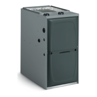
Variable Speed Motor
Locate the motor control board in the blower control box.
Set the HEAT and COOL CFM taps by moving the board
jumpers to the A, B, C, or D positions (see Figure 2)
based on the information found in the Application Table
on page 11. The ADJUST tap on the control board can be
used to raise or lower the table CFM’s. The (+) tap will
raise the table CFM by 10%, and the (–) tap will lower the
table CFM by 12%. IMPORTANT: When changing the
control taps, the high voltage must be off in order for
the new settings to take effect.
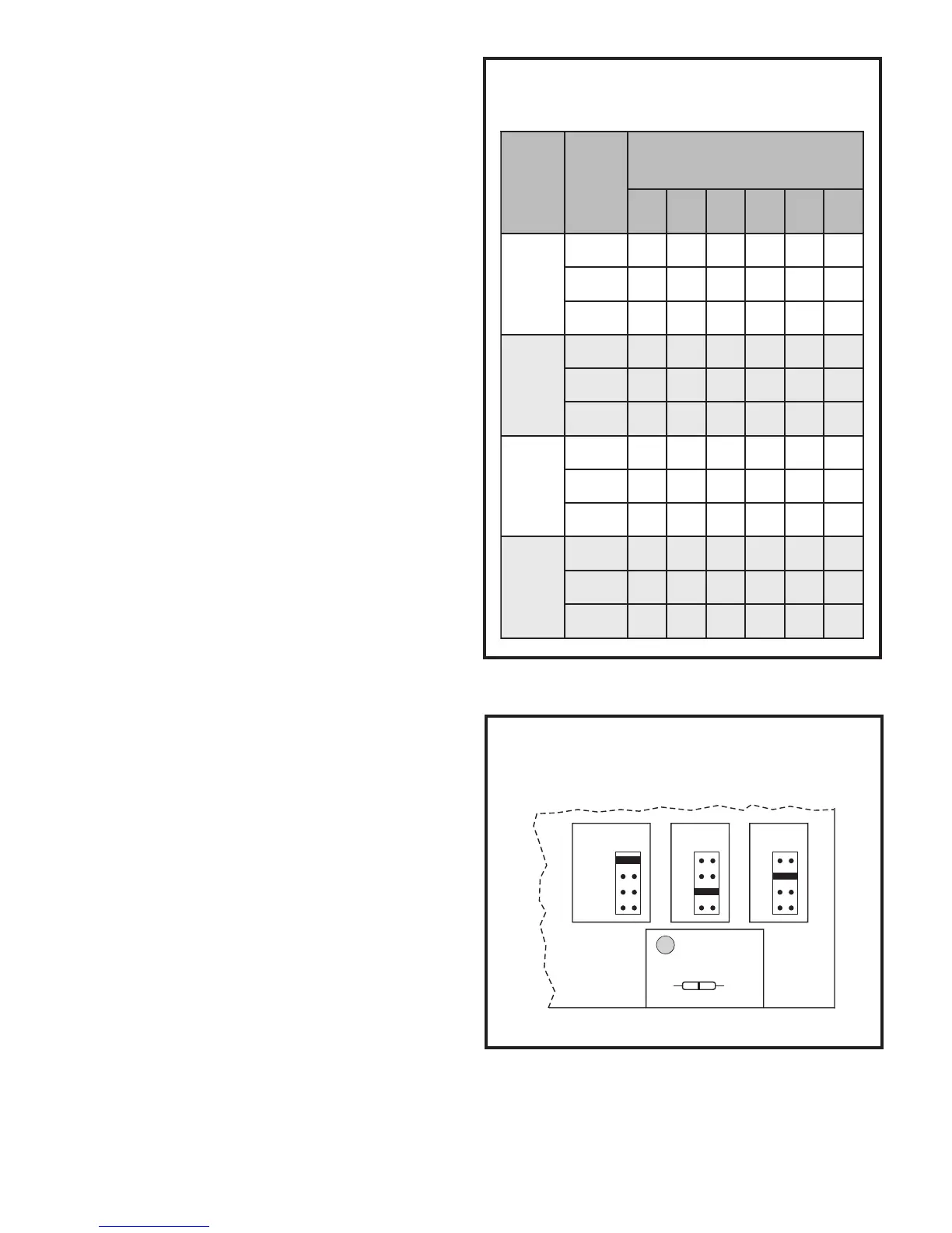
ledoM
rewolB
deepS
citatSlanretxE@MFC
.C.W.nierusserP
1.0 2.0 3.0 4.0 5.0 6.0
80CFE
woL385365755145225374
muideM268558438497847776
hgiH951169019201759178497
21CFE
woL 838 728 808 877 647 996
muideM 5621 5521 5321 5121 3711 8111
hgiH 8531 0431 1131 2821 1321 9711
61CFE
woL161135118311511119010501
muideM965114517051064150411431
hgiH967153713071626107519841
02CFE
woL 2361 6651 1851 4451 2841 7141
muideM 3612 3012 8502 0002 7491 5581
hgiH 8932 4932 6622 0812 9012 2402
Blower Performance Chart
PSC Motor
Table 2
This model is designed for use with heat pumps as
well as air conditioning systems. The motor control
board needs to sense a signal on the “O” thermostat
wire in order to use cooling delay timing. For a
DEHUMIDIFY
CUT TO ENABLE
COOLHEATADJUST
NORM A
B
C
D
A
B
C
D
(+)
(–)
TEST
D1
Motor Board Taps and
Dehumidify Resistor
Figure 2