506303-01
Page 32 of 40 Issue 0938
It is recommended that this furnace be inspected by a
qualified service technician at the beginning of each heating
season.
Filters
Filters should be checked at least every 6 weeks. Disposable
filters should be replaced when dirty, and cleanable filters
should be cleaned regularly. It is important to keep the air
filters clean, as dirty filters can restrict airflow and the blower
and induced draft motors depend upon sufficient air flowing
across and through them to keep from overheating.
Lubrication
The blower motor and induced draft motor are pre-lubricated
by the manufacturer and do not require further lubricating
attention. However, the motors should be cleaned periodically
to prevent the possibility of overheating due to an accumulation
of dust and dirt on the windings or on the motor exterior.
MAINTENANCE
Condensate Collection and Disposal System
Check the condensate drain line periodically for blockage.
Visual inspection of condensate flow can be done easily
while the furnace is in operation. Use a flashlight to illuminate
the discharge end of the condensate drain that is placed in
the sewer opening. If the condensate drain line becomes
blocked or plugged, the furnace will not operate properly.
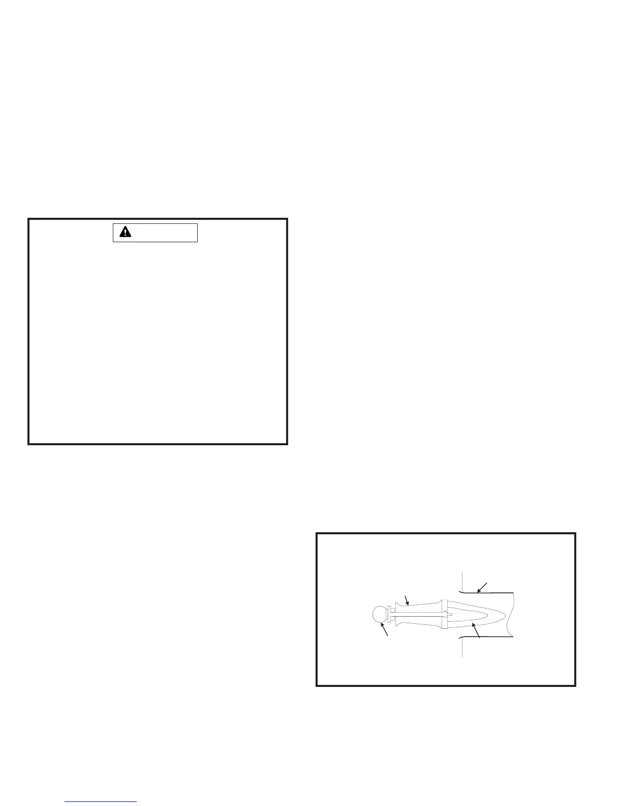
Burners
Light the burners and allow to operate for a few minutes to
establish normal burning conditions. Observe the burner
flames. Compare this observation to Figure 43 to determine if
proper flame adjustment is present. Flame should be
predominantly blue in color and strong in appearance. Check
that all burners are lit, and that the flame does not impinge on
the sides of the heat exchanger.
Distorted flame or yellow tipping of the natural gas burner
flame, or long yellow tips on propane, may be caused by
lint accumulation or dirt inside the burner or burner ports, at
the air inlet between the burner and manifold pipe, or
obstructions over the burner orifice.
Use a soft brush or vacuum to clean the affected areas.
Connect the desired speed tap to the “EAC” terminal and
the neutral tap to the neutral terminal on the ignition control
(refer to the furnace wiring diagram). The ignition control
will control the motor’s operation, including a nominal 20-
second “on” delay with a call for heat and a nominal 180-
second “off” delay when the thermostat is satisfied. It will
also operate the motor on a call for cooling, with no “on” or
“off” delays.
Verify that the unit is operating at the desired speed and
within the rise range as shown on the unit rating plate.
The correct replacement motor must be installed as
soon as possible to ensure continued satisfactory
operation of the furnace.
Failure to follow the safety warnings exactly could result
in dangerous operation, serious injury, death, or property
damage.
Improper servicing could result in dangerous operation,
serious injury, death, or property damage.
• Before servicing, disconnect all electrical power to
furnace.
• When servicing controls, label all wires prior to
disconnecting. Reconnect wires correctly.
• Verify proper operation after servicing.
WARNING
ELECTRICAL SHOCK, FIRE,
OR EXPLOSION HAZARD
Typical Flame Appearance
Figure 43
Heat
Exchanger
Burner
Flame
(Blue Only)
Burner
Gas
Manifold
 Loading...