506303-01
Page 6 of 40 Issue 0938
The venting system must be supported with mounting straps
to prevent any weight load from being applied to the vent
blower. Horizontal vent pipe must be supported every 5'
and vertical pipe should be supported every 10' to prevent
sagging and provide rigid support.
When a furnace is installed as direct vent, provisions for
ventilation air should follow the same requirements as if
installed as non-direct vent. Proper ventilation air is
necessary to maintain furnace component temperatures
within acceptable limits.
All vents passing through floors, ceilings, and walls must
be installed in accordance with National Fuel Gas Code,
ANSI Z223.1/NFPA 54 (latest edition).
The length of flue pipe exposed to outdoor conditions should
be kept to a minimum. When the installation requires more
than 3 feet of flue pipe be exposed to outdoor conditions,
insulating the exposed flue pipe with 1/2” Armaflex or
equivalent is recommended. In climates with design
temperatures below zero degrees (F), 3/4” Armaflex or
equivalent is recommended.
Materials
All pipe, fittings, primer, and solvent cement must conform
with American National Standard Institute and the American
Society for Testing and Materials (ANSI/ASTM) standards.
The solvent shall be free flowing and contain no lumps,
undissolved particles, or any foreign matter that adversely
affects the joint strength or chemical resistance of the cement.
The cement shall show no gelation, stratification, or
separation that cannot be removed by stirring.
Refer to Table 2 for approved piping and fitting materials.
Canadian Applications Only:
PVC pipe, fittings, primer and solvent cement used to vent
this applicance must be certified to ULC S636 and supplied
by a single manufacturer as part of an approved venting
system. In addition, the first three feet of vent p ipe from
the furnace flue collar must be accessible for inspection.
Models that may be installed as a horizontal furnace include
a horizontal drain kit. In Canada this dain kit must be
replaced by a locally available IPEX Drain Kit #196014. For
Local IPEX Canadian Customer Service Center and Kit
availability call IPEX at 1-866-473-9462.
The primers and solvents used must also meet ASTM
specifications. PVC primer is specified in ASTM F656. Use
PVC solvent as specified in ASTM D2564 and ABS solvent
cement as specified ASTM D2235. Low temperature solvent
cement is recommended. Metal or plastic strapping may
be used for vent pipe hangers.
• Restrictor plate in inlet pipe: Insert a 3" to 36" section
of PVC pipe (field supplied) into the collar. Use high
temperature RTV sealant to attach PVC pipe to collar.
Install the restrictor plate in the end of the inlet pipe just
installed. Attach either a field-supplied coupler or 90°
elbow to the end of the PVC pipe to keep the restrictor
plate in place. Use high temperature RTV sealant to
attach the coupler or elbow to PVC pipe.
• Restrictor plate in elbow: Insert a 3" to 36" section of
PVC pipe (field supplied) into the collar. Use high
temperature RTV sealant to attach PVC pipe to collar.
Attach a 90° elbow (field supplied) to the PVC pipe. Use
high temperature RTV sealant to attach elbow to PVC
pipe. Install the restrictor plate into the elbow.
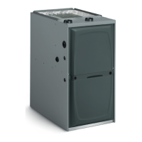
Two different sized inlet restrictor plates are supplied with the
furnace (2" and 3"). Use the proper restrictor plate for the
furnace model.
Also included in the plastic bag containing the inlet air
restriction plate is a flue pipe screen (see Figure 2). In all
installations, this screen should be installed at the
termination of the flue pipe and is designed to keep objects
out of the flue pipe.
For either type of installation (direct or non-direct vent),
special venting considerations must be followed. Refer to
the proper section in pages 11 – 15 for the type of furnace
and venting being installed.
If at any time in the future the installation of this furnace
is changed to require outside fresh air for combustion,
the inlet air restrictor plate must be removed. Failure
to remove the inlet air restrictor could cause improper
operation that can result in a fire hazard or carbon
monoxide injury.
WARNING
Flue Pipe Screen
The flue pipe screen should be
installed at the termination of the flue
pipe in all installations.
Figure 2
Inlet Air Restrictor Plate
The inlet air restrictor plate must be
installed in all installations using inside
air for combustion (non-direct vent).
 Loading...