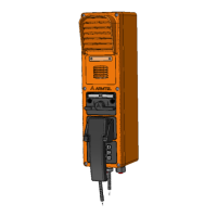
DWEX DIGITAL LOUD-SPEAKING EXPLOSION PROOF CALL STATION
User Manual
armtel.com page 37/40
info@armtel.com © Armtel
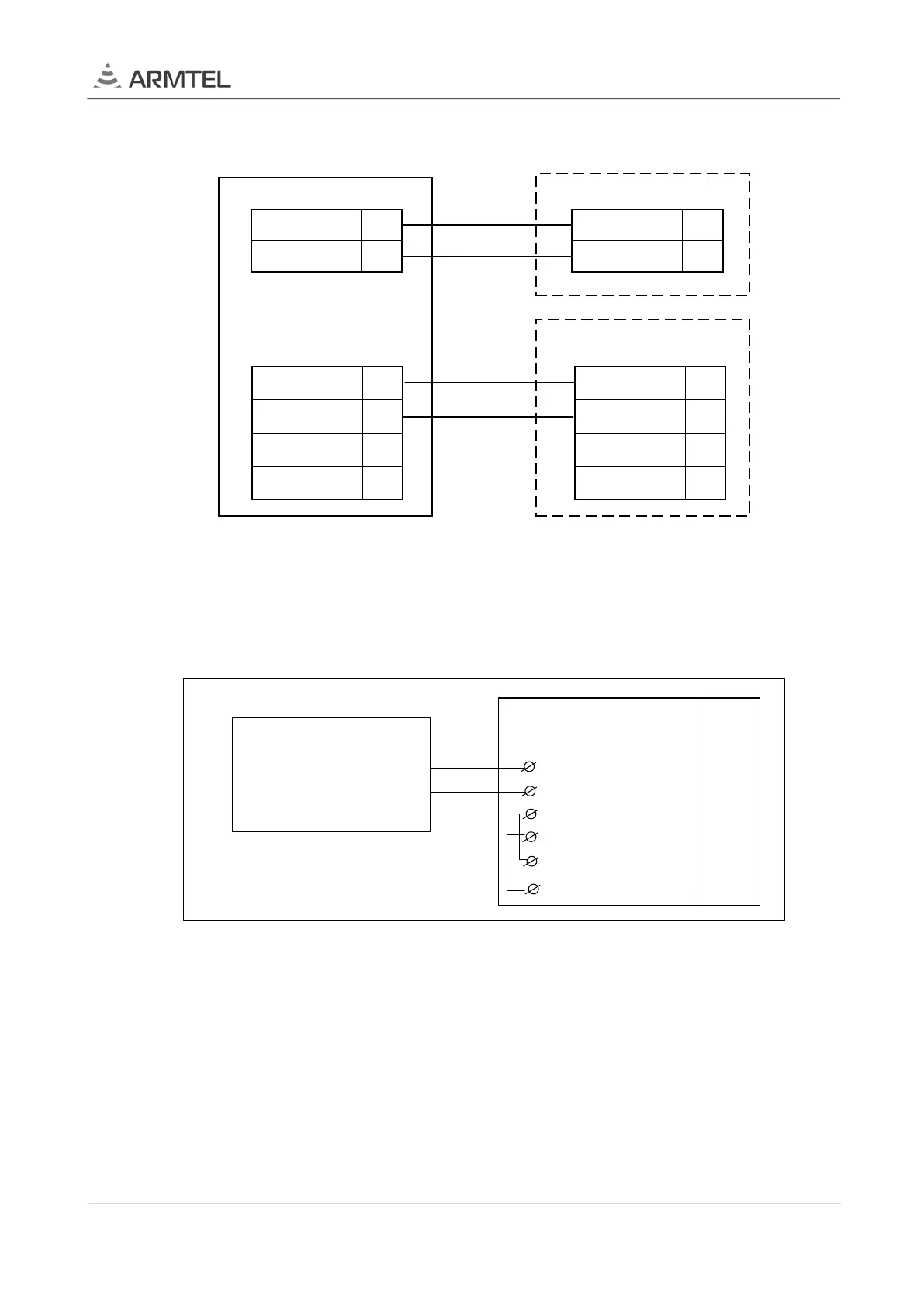
Diagram of internal connection of the auxiliary amplifier is illustrated at Figure B.1.
Auxiliary
amplifier
Х1
Х2
1
1
2
2
3
4
IN_25W+
IN_25W-
B
A
+0V
-48V
1
2
IN_25W+
IN_25W-
Main board
Х2
Terminal block
1
2
3
4
25W_OUT_1
25W_OUT_2
+POW_25W
-POW_25W
Figure B.1 – Connection of auxiliary amplifier
Connection of Uk
0
interface line and use of “phantom” power supply (supply voltage is
supplied via interface circuits + Ua, -Ub) is illustrated at Figure B.2.
DWEx
+Ua
-Ub
+ U_POWER
5
6
7
8
- U_POWER
Central
exchange
( DCN, IPN)
9
10
+ U_FANTOM
- U_FANTOM
Terminal block
Pin No
Figure B.2 – Connection of Uk
0
interface line and use of “phantom” power supply
Note – Power supply of DWEx versions with auxiliary amplifier 25W by “phantom” power
supply circuit is prohibited.