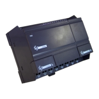
Controladores lógicos programables PLC baja gama expandibles entradas digitales AC 74368-SR22MRDC ARRAY Manual Ingles www.viaindustrial.com
Controladores lógicos programables PLC baja gama expandibles entradas digitales AC 74368-SR22MRDC ARRAY Manual Ingles www.viaindustrial.com
Line diagram/ Symbol in SR Pin Description
Analog Input 1, can be selected as: the value calculated from the
analog input IA through the math formula, or the preset analog
Analog Input 2, can be selected as: the value calculated from the
analog input IA through the math formula, or the preset analog
If the comparing condition between Input 1 and Input 2 is YES,
Q will be 1, and otherwise Q will be 0.
If the property pin of the output P is connected with the
properties pin of the SLCD, the parameter of this function block
will be transferred to HMI.
Only SR-12MRD, SR-12MTD, SR-22MRD, SR-22MTD types have this function.
This function is used in the analogue input instructions.
The value of the analog input (IA), which the CMPR compares, is valued out through
math formula and is not the actual input voltage value. And the math formula is
If one temperature sensor is connected to the IA terminal of the DC type main
machine, and the voltage value of this temperature sensor is the linear relationship
with the temperature. At 1¡æ, the actual voltage of IA1 terminal is 0V; and at 50 ¡æ,
the actual voltage of IA1 terminal is 7V. From the above math formula, we can get
that A=7 and B=1. That is too say that when the temperature is 7¡æ higher, the
voltage will be 1V higher. So we have the following equalities. Example 1:
7(A)*7(IA)+1*(B)=50¡æ. Example 2: 7*(A)*6(IA)+1(B)=43¡æ. And now if you put
the values of A and B into the SR main machine, when the pin of IA1 tests the voltage
is 6V, this CMPR will display 43¡æ automatically on SR-HMI.
1. In this example, A is the proportion parameter. When the temperature is higher 7
¡æ, the voltage is 1V above. So value of A is 7.
2. B is the deviation parameter. That is to say that at 1¡æ the voltage of IA is 0V.
3. IA is the tested voltage value of the input terminal A.
Actually the value of A and B don’t need for you to calculate by pen. We
have put the math formula into SR-WRT and the free software SUPER CAD. You
only need to connect the sensor to the related analog input (IA) then the value of A
and B will be written into SR machine according to the related methods.
Here we explain the method in SUPER CAD:
Connect the SR main machine and your PC via SR-CP. Power on the SR
main machine and open the SUPER CAD software. Then select [Set Analog