Do you have a question about the ARRI Master Grip MRW-1 and is the answer not in the manual?
Explains risk levels (DANGER, WARNING, CAUTION, NOTICE) and their associated alert symbols for safety.
Details what a complete delivery should include and advice for checking package contents.
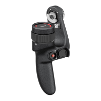
Highlights key features like versatile controls, design, and ease of use for ARRI Master Grips.
Describes the four available versions of the Master Grip based on side and control type.
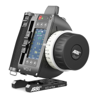
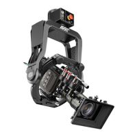
Illustrates various connection configurations for Master Grips with different camera systems.
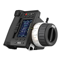
Defines LBUS as an ARRI/cmotion bus standard for communication between lens motors and control devices.
Outlines the four main screens accessible via swipe gestures on the Master Grip interface.
Explains the indicator gauge, its limits, and the meaning of different gauge colors.
Describes how to access and navigate setup menus for each top-level screen.
Illustrates the mapping of physical controls to the joystick and button interface screens.
Details assigning REC, LIM, MAX SPD, SPD+/-, and OVR functions to controls.
Explains assigning FIZ, F/I, and SET TO F/I/Z for axis control and toggling.
Describes assigning user buttons, control locks, and focus tracking functions.
Provides a step-by-step guide on how to use the override function to control lens axes.
Explains how override status is indicated on the Master Grip display.
Lists part numbers and brief descriptions for different Master Grip models.
Details the various Master Grip sets available, including their contents.
Lists different types of LBUS cables with their specifications and lengths.
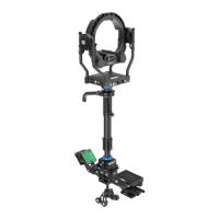
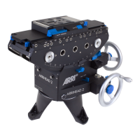
Describes various mechanical accessories for the Master Grips.
Details sets of mechanical accessories for Master Grips.
Shows the pin configuration of the LBUS connector and its functions.
Outlines the compatibility of Master Grips with various cameras and motor controllers.
| Brand | ARRI |
|---|---|
| Model | Master Grip MRW-1 |
| Category | Camera Accessories |
| Language | English |