4 BDA Broadband Telecommunications Drop Amplifier 485855-001 Rev B
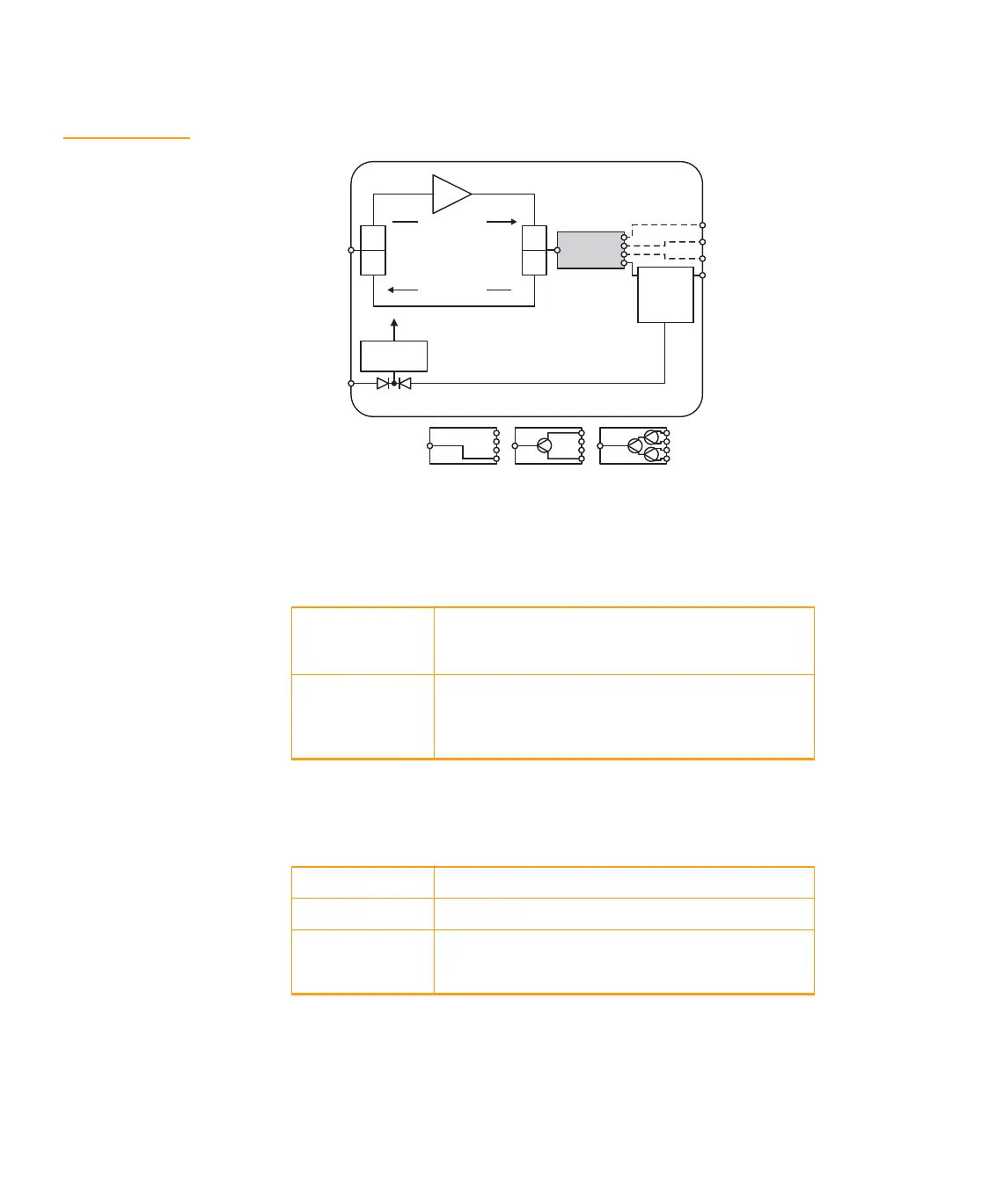
Figure 2 illustrates a functional block diagram of the BDA-** drop amplifier.
Figure 2
Block diagram
Document Conventions
Before you begin using the BDA-**, familiarize yourself with the stylistic conventions used in
these installation instructions:
Before You Begin
Unpack the unit carefully and verify that you have received:
Power
12 Vdc
Vdc
dc
regulator
Internal
splitter
RF
input
H
L
H
L
Forward path
Return path
RF out 1 and
Remote power/RF
RF out 2
RF out 3
RF out 4
RF RF/
dc in
dc out
Internal splitter
4 out1 out 2 out
SMALL CAPS Denotes silk screening on the equipment, typically
representing input/output (I/O) and power supply
connections
* (asterisk) Indicates that more than one version of the same
model number exists and the information applies to all
models; when the information applies to a specific
model, the complete model number is given
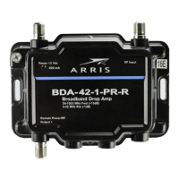
BDA-** 1 GHz drop amplifier
BDPS* Power supply. Included with models BDA-**/PS
Optional
Accessory: BDP
100/PI
1 GHz indoor power inserter for remote powering of
the amplifier


 To Next Page